APF Spectrograph Photos
APF Wiring Internal to the Galil Control Box,  EL-3508
Schematic: schematics\APF_interconnections_sh_1.pdf
Page last updated: August 22, 2012
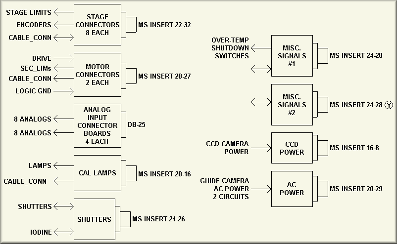
Simplified Drawing
Simplified Drawing
Simplified Drawing
Simplified Drawing
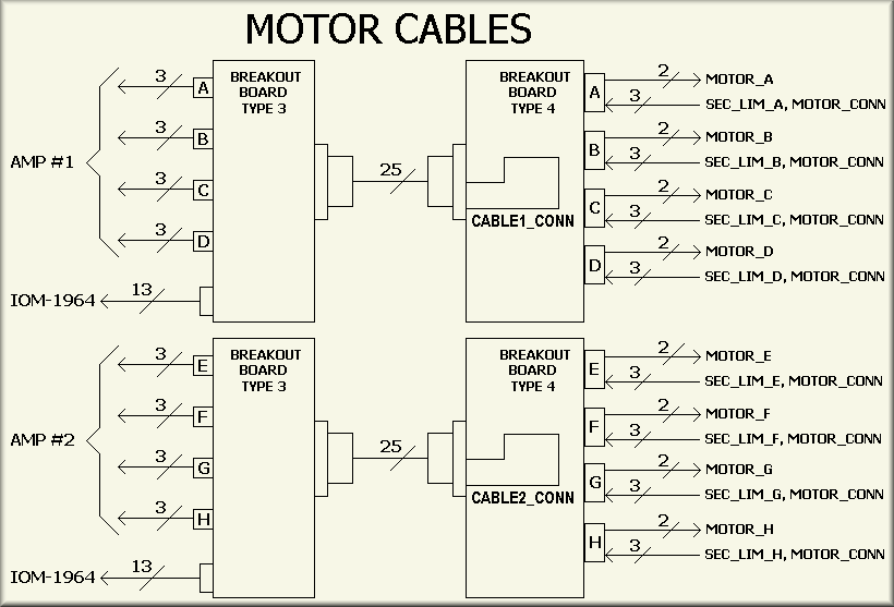
Sheet 2, Motor Cables,  , APF_interconnections_sh_2.pdf
Simplified Drawing
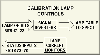
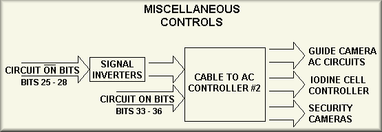
Sheet 3, Lamps and Cooling APF_interconnections_sh_3.pdf
Simplified Drawing
Simplified Drawing
Sheet 4, Cable Connected and Secondary Limits APF_interconnections_sh_4.pdf
| Signal | IOM Pin |
DB-37 Pin |
Signal | IOM Pin |
DB-37 Pin |
|
|---|---|---|---|---|---|---|
| ADC & CAM GND | 1 | 1 | IOD_MOTOR_CONN | 35 | 29 | |
| ADC_MOTOR_CONN | 15 | 20 | IOD_MOTOR_ENCOD_CONN | 36 | 11 | |
| ADC_MOTOR_ENCOD_CONN | 16 | 2 | IOD_LOAD_ENCODER_CONN | 37 | 30 | |
| ADC_LOAD_ENCODER_CONN | 17 | 21 | IOD_LIMIT_CONN | 38 | 12 | |
| ADC_LIMIT_CONNN | 18 | 3 | SLT_MOTOR_CONN | 39 | 31 | |
| CAM_MOTOR_CONN | 19 | 22 | SLT_MOTOR_ENCOD_CONN | 40 | 13 | |
| CAM_MOTOR_ENCOD_CONN | 20 | 4 | SLT_LOAD_ENCODER_CONN | 41 | 32 | |
| CAM_LOAD_ENCODER_CONN | 21 | 23 | SLT_LIMIT_CONN | 42 | 14 | |
| CAM_LIMIT_CONN | 22 | 5 | DEW & H GND | 1 | 33 | |
| CMR & CAL GND | 1 | 24 | SLT_MOTOR_CONN | 45 | 15 | |
| CMR_MOTOR_CONN | 25 | 6 | SLT_MOTOR_ENCOD_CONN | 46 | 34 | |
| CMR_MOTOR_ENCOD_CONN | 26 | 25 | SLT_LOAD_ENCODER_CONN | 47 | 16 | |
| CMR_LOAD_ENCODER_CONN | 27 | 7 | SLT_LIMIT_CONN | 48 | 35 | |
| CMR_LIMIT_CONN | 28 | 26 | 49 | 17 | ||
| CAL_MOTOR_CONN | 29 | 8 | 50 | 36 | ||
| CAL_MOTOR_ENCOD_CONN | 30 | 27 | 51 | 18 | ||
| CAL_LOAD_ENCODER_CONN | 31 | 9 | 52 | 37 | ||
| CAL_LIMIT_CONN | 32 | 28 | MOT1 & MOT2 GND | 1 | 19 | |
| IOD & SLT GND | 1 | 10 | - | - | - |
| Signal | AMP J3 | DB-9 | ADC_SEC_LIM | 24 | 1 |
|---|---|---|
| CAM_SEC_LIM | 38 | 6 |
| CMR_SEC_LIM | 8 | 2 |
| CAL_SEC_LIM | 23 | 7 |
| IOD_SEC_LIM | 37 | 3 |
| SLT_SEC_LIM | 7 | 8 |
| DEW_SEC_LIM | 22 | 4 |
| (RESERVED) | 36 | 9 |
| GND | 3 | 5 |
Sheet 5, Home, Primary Limits and DC Power APF_interconnections_sh_5.pdf
| SIGNAL | AMP J3 | J15 | SIGNAL | SIGNAL | AMP J3 | J15 | SIGNAL | |
|---|---|---|---|---|---|---|---|---|
| REV_LIM_A | 11 | 1 | _REV_LIM | REV_LIM_E | 11 | 7 | E_REV_LIM | |
| REV_LIM_B | 12 | 14 | _REV_LIM | REV_LIM_F | 12 | 20 | F_REV_LIM | |
| REV_LIM_C | 13 | 2 | _REV_LIM | REV_LIM_G | 13 | 8 | G_REV_LIM | |
| REV_LIM_D | 14 | 15 | _REV_LIM | REV_LIM_H | 14 | 21 | (RESERVED) | |
| - | - | - | - | - | - | - | - | |
| - | 15 | 3 | - | FWD_LIM_H | 15 | 9 | (RESERVED) | |
| - | - | - | - | - | - | - | - | |
| HOME_A | 26 | 16 | A_HOME | HOME_E | 26 | 22 | E_HOME | |
| HOME_B | 27 | 4 | B_HOME | HOME_F | 27 | 10 | F_HOME | |
| HOME_C | 28 | 17 | C_HOME | HOME_G | 28 | 23 | G_HOME | |
| HOME_D | 29 | 5 | D_HOME | HOME_H | 29 | 11 | (RESERVED) | |
| - | - | - | - | - | - | - | - | |
| FWD_LIM_A | 41 | 18 | A_FWD_LIM | FWD_LIM_E | 41 | 24 | E_FWD_LIM | |
| FWD_LIM_B | 42 | 6 | B_FWD_LIM | FWD_LIM_F | 42 | 12 | F_FWD_LIM | |
| FWD_LIM_C | 43 | 19 | C_FWD_LIM | FWD_LIM_G | 43 | 25 | G_FWD_LIM | |
| - | - | - | - | GND | 35 | 13 | GND |
| SIGNAL | J16 | TB1 |
|---|---|---|
| ISO 5V | A | 1 |
| ISO 5V RTN | B | 2 |
| ISO 5V | C | 3 |
| - | - | 4 |
| ISO 5V RTN | D | 5 |
| - | - | 5 |
| +48V | E | 8 |
| +48V RTN | F | 10 |
| +48V | G | 9 |
| +48V RTN | H | 11 |
Sheet 6, Shutters Wiring APF_interconnections_sh_6.pdf
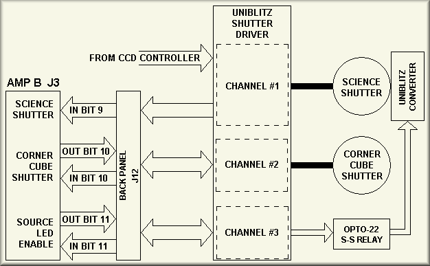
Simplified Drawing
Sheet 7, 48V Supply Control and Status APF_interconnections_sh_7.pdf
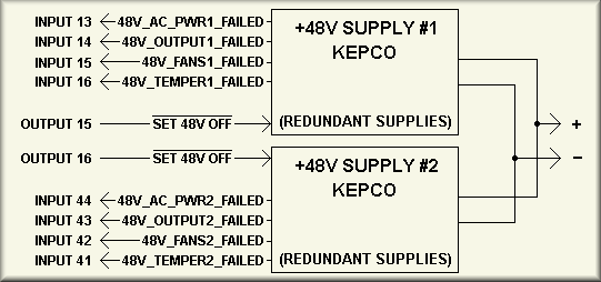
Simplified Drawing
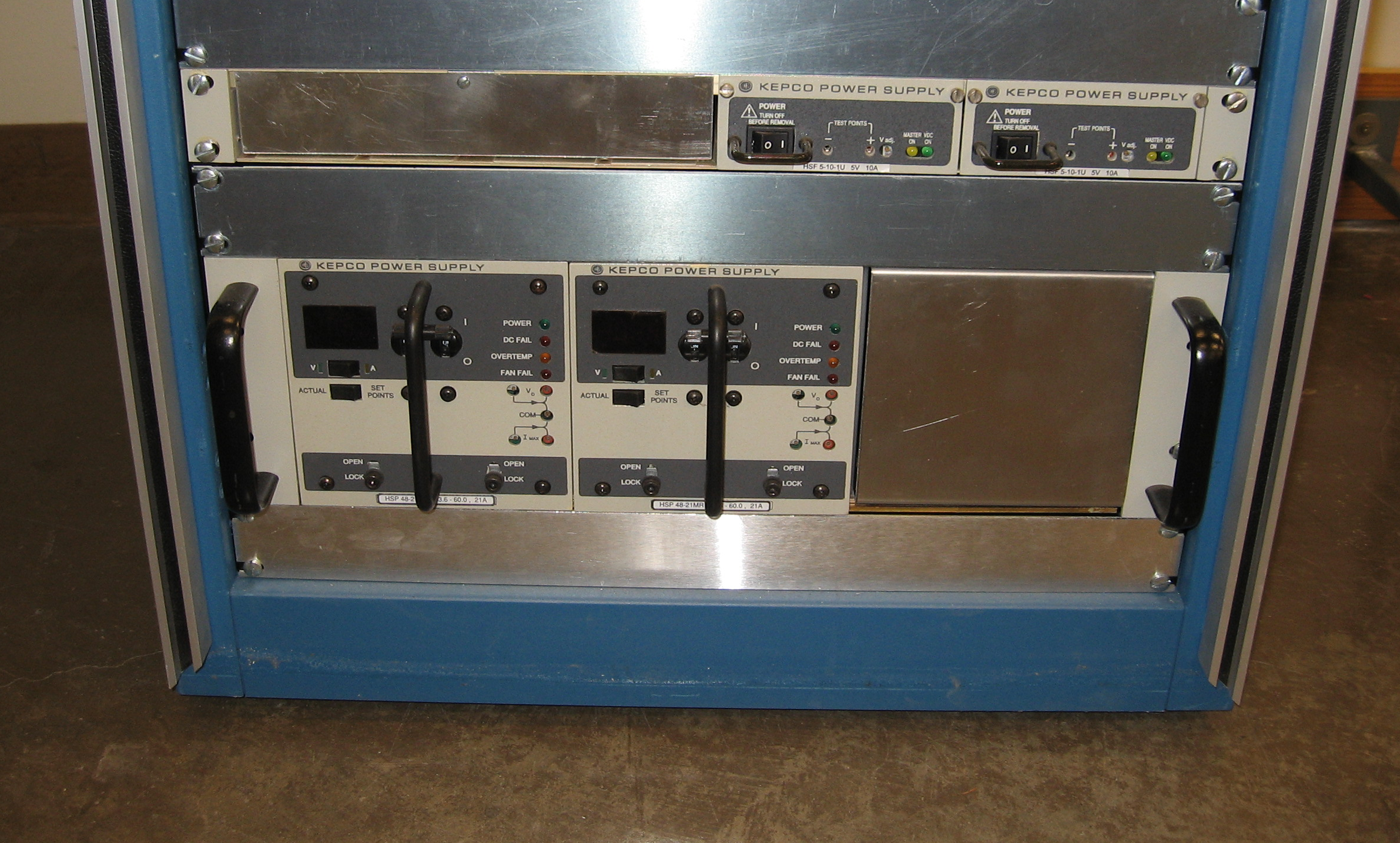
The power for the servo motors for the APF instrument is provided by a pair of Kepco HSP 48-21MR 48 volt supplies. The supplies are sized and arranged such that if one were to fail the other supply is capable of powering all of the servos. The supplies are each powered via a separate Pulizzi channel. That is, supply one is on Pulizzi channel 3 and supply two is on channel 4. Note that while the Pulizzi power controller can be controlled via software, it is set for default operation at power up - that is, channel 1 comes on first then about a second later channel 2 come on and so forth until all 8 channels have come on.
As is depicted on the left side of the above drawing, each supply has one control input and four status outputs. The ~SET_48V_OFF signals can be used to inhibit the DC output of the supply. When held low, the output voltage is removed, the DC FAIL indicator on the front panel of the supply comes on, and the 48V_OUTPUTn_FAILED signal goes high. The AC_PWRn_FAILED signal goes high if power is removed from the unit. Note that if the AC power is removed from the supply the three other output bits are invalid. The 48V_FANSn_FAILED and 48V_TEMPERn_FAILED signal states can not be tested but the wiring is tested by removing the power supply's I/O connector. When removed, these two inputs float high.
Click for larger view
Sheet 8, 5V Supply Control and Status APF_interconnections_sh_8.pdf
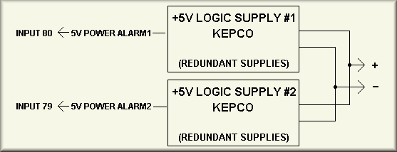
Simplified Drawing
Sheet 9, Ion Pump Controller Monitoring APF_interconnections_sh_9.pdf
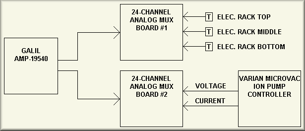
Simplified Drawing
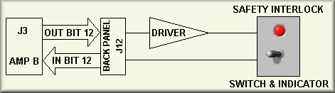
Sheet 10, Stage Safety Interlock Switch APF_interconnections_sh_10.pdf