APF Spectrograph Electronics
APF Cooling System,  EL-3505
Schematic: schematics\APF_cooling.pdf
Page last updated: August 22, 2012
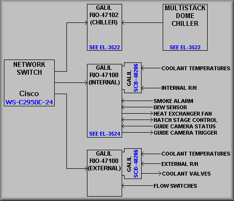
Sheet 1, Fig. 1
The APF cooling system is actually made up of four different components. First is the dome chiller system that is intended to keep the building at a temperature close to the night time outdoor temperature. The system is located in a housing to the ENE of the dome at the base of the driveway leading to the dome. Please refer to the EL-3522 write up. Next is the Cryo-Tiger cooling system connected to the CCD dewar. This commercial system is monitored via the temperature sensing diode located on the back of the CCD. Control of the detector temperature is facilitated by the use of a heater resistor also located at the back of the CCD. The last commercial cooling system is the Peltier cooler attached to the detector in the guide camera.
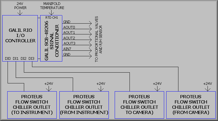
The Lick-built system is comprised of four proportional valves and controllers, various RTD temperature sensors, a commercial chiller, and a pair of Galil RIO I/O controllers. Three of the four proportional valves are used to control the coolant flow, and thus the temperature of three circuits. Each of these valves are controlled via a PID filter to maintain a given temperatureThe fourth valve is used to provide a bypass path for the coolant in the event that all three circuits are throttled down due to very low ambient temperature in the instrument. The first cooling circuit is used to cool the calibration lamps located in the integrating sphere. These are the 10 and 50 watt quartz halogen lamps.
Cooling is effected by the use of two multi-wrap coils of copper tubing, one on the normal lamp and one on the back-up lamp. The second circuit supplies a Lytron 6106 heat exchanger located at the bottom of the instrument housing. Mounted above the heat exchange is a 24V DC, 118 cfm fan that is controlled via digital output DO1 of the internal RIO controller. The heat exchanger and fan are attached to tube-like structure, commonly known as the snorkel, that extends to the top of the instrument where warmer air is drawn in and then blown through the heat exchanger.
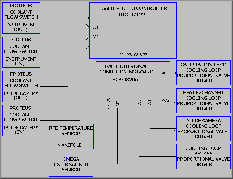
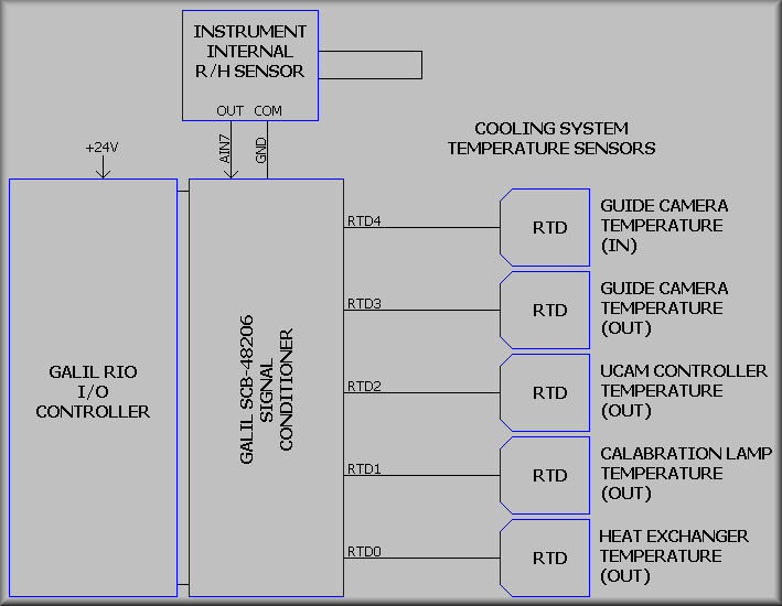
Sheet 1, Fig. 2
Fig. 2 above shows the middle section from the schematic. At the top is the external RIO controller with its attached SCB-48206 RTD signal condioner board.
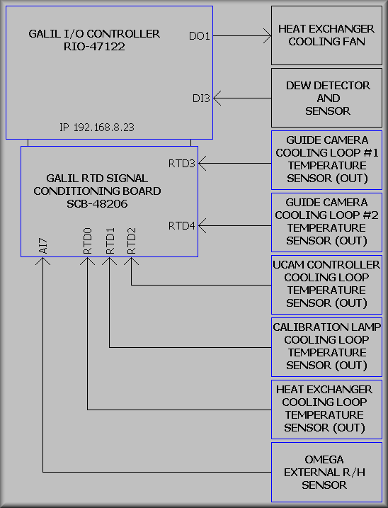
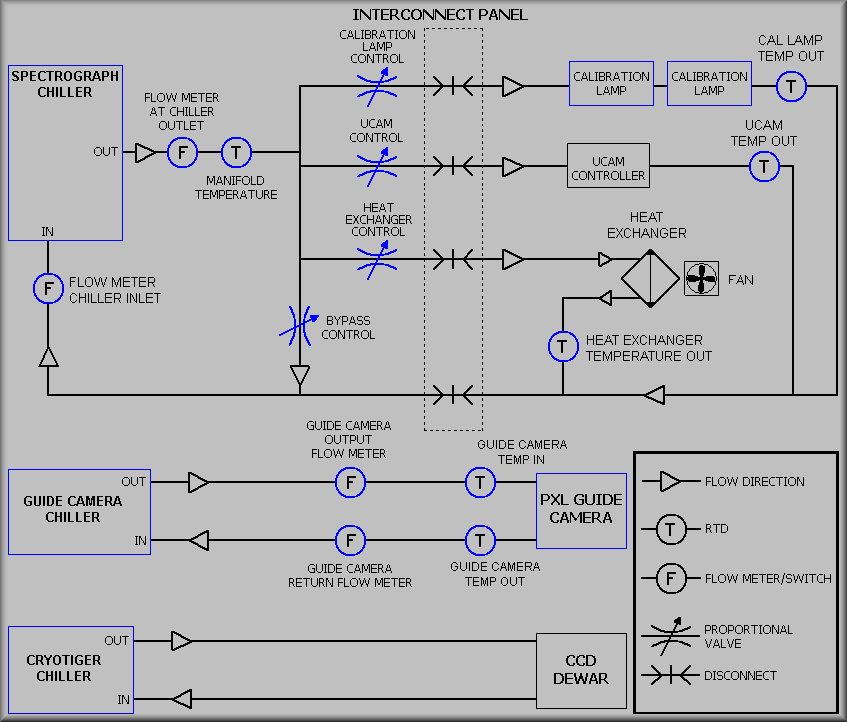
Sheet 1, Fig. 3
Sheet 2, , APF_cooling_sh_2.pdf
Sheet 3, , APF_cooling_sh_3.pdf
Simplified Drawing
Simplified Drawing
Sheet 4, APF_cooling_sh_4.pdf
Simplified Drawing
Sheet 5, APF_cooling_sh_5.pdf
Simplified Drawing