Electronics
This section contains descriptions of the overall electronics for the ADC project. It corresponds to the 'Block Diagram' tab in the schematics binder.
Overall Block Diagram, EL-3601
| Sheet 1 | Block diagram - signal flow | |
| Sheet 2 | Block diagram - cabling | |
| Sheet 3 | Block diagram - internal cabling |
Schematic: schematics\ADC_block_SH1.sch.pdf
Page last updated:
February 24, 2005
ADC Electronics Summary of Operation
The ADC electronics consist of a 19” rack mounted control box and the prism stage mounted equipment. At the prism stage the following components move and monitor the stage position:
· DC Servomotor with encoder
· Load encoder
· Limit and Home Hall-effect switches
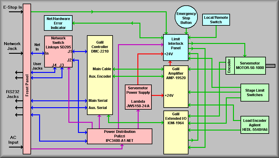
As shown on the block diagram, schematic EL-3601, sheet 1, the control electronics consist of:
· Interconnect panel
· Network hub
· AC power controller
· Galil DMC-2210 servomotor controller
· Galil AMP-19520 servo amplifier
· Galil IOM-1964 64-channel I/O module
· 24V Power supply
· Lick interlock panel
Starting at the left side of the diagram, the interconnect panel will actually consist of the three front panels on the electronics box. The first panel, the output panel, holds the connectors for connecting to the ADC stage. The second panel holds the connectors for the observatory E-Stop signal, the manual paddle, and the local/remote paddle and is part of the interlock panel. The last panel, the input panel, holds the various communications connectors and the AC power input connector.
Communications:
The only connection required to talk to the ADC electronics is the network
cable connected the control computer. This connection is made on the input
panel via a ruggedized RJ45 connector. This connector is similar to a standard
bayonet style MS connector but it also allows for use of a standard RJ45
connector if needed. The serial connectors on the input panel are there for
troubleshooting problems. They include serial connections directly to the
Galil controller and to the Pulizzi power controller. The two network jacks
are wired to the network hub contained if the electronics box and provide
a convenient outlet for a laptop computer.
AC Power:
The input AC power is connected to the electronics box via a front panel mounted
RFI input module. This module is wired to the Pulizzi power controller and
the network hub.
The Pulizzi power controller is used to give software control of power cycling
of the network hub, Galil controller, the 24 volt power supply, and the interlock system.
The Pulizzi also allow power up and power down sequencing via the setting of
variable if desired. When the power is applied to the electronics box the first equipment to turn on is the Pulizzi controller. In a few seconds, the other equipment comes on one at a time with about a one second delay between each Pulizzi output.
Instrument control:
The ADC control system is built around the Galil DMC-2210 servomotor controller.
The controller generates the drive signal and monitors the status of the
instrument. The status consists of primary and secondary limits, stage HOME signal, interconnection of cable signals, and various monitor inputs such
as ambient temperature and 24V power level.
The motor signal is sent to the servo amplifier that amplifies the power to
the motor. The gain of the amplifier is jumper selected for 1.0 Amp/volt. This
drive signal is then wired to the ADC stage motor shown via the interlock system.
If no lock out conditions exist, the motor power continues on to the stage
on the right hand side of the sheet. The amplifier module also contains connectors for the various limits switches and encoder inputs.
64-Channel I/O module:
The extended I/O module connects to the Galil controller and accepts the input
signals from the extra limit switches, cable connected signals, and emergency
stop signals. The only output used at this time is a pulse that is sent to
a timer circuit that will indicate a network or hardware error via an LED
indicator on the interlock front panel. If the circuit is not continuously pulsed,
the LED will be lit indicating that the controller is not generating the
pulse and thus unable to talk over the net or the controller is stopped. For the schematic showing the I/O bit assignments. Click Here for outputs and Click Here for inputs.
Interlock panel:
The interlock system performs the following functions:
· Disconnects power to the motor if a secondary limit is tripped
· Manages the Local/Remote operation
· Allows for the use of the emergency null system
· Sends status information back to the controller
Most importantly, the interlock system controls the power flowing to the stage
motor. If an error conditions occurs, the interlock system will open the appropriate
relay disconnecting motor power. If a secondary limit is the cause of the error,
the interlock system will allow a movement (retract) toward the null position
by actuating the bypass mode switch.
The Local/Remote function allows a technician to control the ADC motion either
from a hand paddle attached either to the front panel of the electronics box or at the mating connector at the instrument. When the manual paddle is selected
for remote operation a set of two pushbuttons are available to manually move
the stage. The controller is sent a signal that the paddle is in
use and will not attempt to move the stage. Note that the local movement mode
removes the restrictions of the software limits. The primary and secondary
limits do, however, functioning normally.
The status sent back to the controller includes the position of the local/remote
switch, the secondary limits, the emergency and E-Stop inputs, and the position
of the bypass mode switch.
ADC Stage:
The ADC stage consists of two co-operating prism cells. Each cell runs in opposite
directions as the stage is commanded to move. The null position is the position
where the prisms are closest to each other. The stage limits, as defined
by the Galil controller, are mounted to the forward prism cell. These are
the primary limits, the HOME signal and the secondary limits. A subset set
of limits is also mounted to the aft prism cell but these are only used to
provide position information/conformation. That is, the aft cell HOME signal
should also be active when the forward cell HOME signal is active. The same
applies to the aft cell secondary limits. The aft cell does not have primary
limits because a motor stage can only have one set of primary limits.
A second, or load, encoder is mounted to the end of the ball screw that drives
the two cells. This is a lower resolution encoder that is used to verify motion
at the ball screw when the motor is commanded to move.
(This sheet is intended to show signal flow for the instrument, not fine
detail)
The Keck ADC electronics are centered around a Galil DMC-2210 single axis
motion controller. The ADC stage consists of two prisms that are conjointly
moved closer or further apart to compensate for atmospheric dispersion. Along
with the motion controller, the system consist of the following equipment:
The network hub simply receives the Keck mountain public network connection and provides jacks for the Galil DMC-2210 and the Pulizzi controller. The two unused channels are routed to the front panel of the ADC electronics box to allow for local connection of a laptop, etc. for diagnosing or troubleshooting problems.
The Pulizzi power controller 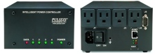 is
used so that the control computer can have control of the power applied to
the Galil controller, the servo motor supply, and the limit interlock panel.
The power controller also facilitates troubleshooting by having local pushbuttons
to control each of the outputs. Another feature, though not presently being
used, is the ability to sequence the outlets in a predetermined order with
predetermined delays for each output. The Pulizzi is normally communicated
with via the network connection but it also has a serial connection that
is brought out to the front panel for troubleshooting.
is
used so that the control computer can have control of the power applied to
the Galil controller, the servo motor supply, and the limit interlock panel.
The power controller also facilitates troubleshooting by having local pushbuttons
to control each of the outputs. Another feature, though not presently being
used, is the ability to sequence the outlets in a predetermined order with
predetermined delays for each output. The Pulizzi is normally communicated
with via the network connection but it also has a serial connection that
is brought out to the front panel for troubleshooting.
The Lambda JWS150-24/A 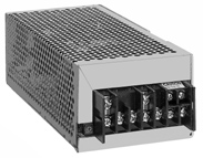 is
a 150 watt, 24 volt power supply used to run the servo amplifier and for
the relay logic used in the limit interlock panel. The supply's AC is controlled
by the Pulizzi power controller so that the software can turn it on after the
motion controller comes on and turn it off before the motion controller.
This helps to make sure that the stage motor does not 'run away' when the
power comes on or goes off.
is
a 150 watt, 24 volt power supply used to run the servo amplifier and for
the relay logic used in the limit interlock panel. The supply's AC is controlled
by the Pulizzi power controller so that the software can turn it on after the
motion controller comes on and turn it off before the motion controller.
This helps to make sure that the stage motor does not 'run away' when the
power comes on or goes off.
The Galil DMC-2210 is a single axis motion controller that communicates either via it's network jack or an RS232/422 port. Under program control, the DMC-2210 generates the drive signal for the stage, monitors input bits, and controls output bits. The user manual is available here.
The Galil AMP-19520 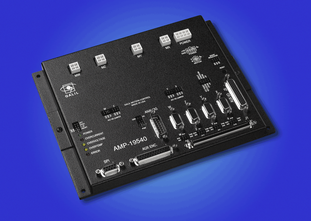 is
a new servomotor amplifier product from Galil. It is capable of running either
standard DC motors or brushless DC motors. The amplifier works the same way
as previous amplifier but can be set for different gain levels. In our case,
we will use the standard 1 volt/amp gain. This current is applied to the
servomotor at 24 volts. Unlike past instruments, the ADC motor power will
be supplied at 24 volts. Because of the use of relays in various circuits
we've used 24V instead of 28V so that we don't stress the relays or shorten
their life. The amplifier connects to the 24V power supply via an 8-pin Mate-n-lock
connector, the servomotor via connector MX, to the stage primary limits and
HOME signal via J3, the load encoder via a high-density DB15S connector,
and the temperature sensors via a DB15P connector. These connectors are all
located on the top face of the amplifier box. A list of jumper settings for the AMP-19520 is available at the lower left hand corner of drawing EL-3610 sheet 2.
is
a new servomotor amplifier product from Galil. It is capable of running either
standard DC motors or brushless DC motors. The amplifier works the same way
as previous amplifier but can be set for different gain levels. In our case,
we will use the standard 1 volt/amp gain. This current is applied to the
servomotor at 24 volts. Unlike past instruments, the ADC motor power will
be supplied at 24 volts. Because of the use of relays in various circuits
we've used 24V instead of 28V so that we don't stress the relays or shorten
their life. The amplifier connects to the 24V power supply via an 8-pin Mate-n-lock
connector, the servomotor via connector MX, to the stage primary limits and
HOME signal via J3, the load encoder via a high-density DB15S connector,
and the temperature sensors via a DB15P connector. These connectors are all
located on the top face of the amplifier box. A list of jumper settings for the AMP-19520 is available at the lower left hand corner of drawing EL-3610 sheet 2.
The Galil IOM-1964 provides optically isolated inputs and outputs. The module is configurable in banks of 8 I/O points each. The module also has provisions for supplying sixteen outputs rated at 500mA each. For configuring to module the user should read Galil's Application Note #1438. For the ADC electronics, blocks 2 - 5, bits 17 - 48, are configured as outputs and blocks 6 and 7, bits 49 - 72 are set to be inputs. None of the high power output are used at this time. The photos below show both the Galil 'stock' version with the cover removed and the Lick version. The Lick version shows that the Galil board is removed from their box and mounted to a panel that is inserted to the instruments electronics cabinet. Also shown on the Lick version is the wiring to connectors J701 and J702.
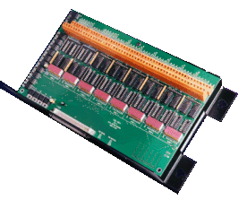
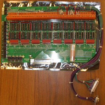
The left hand picture is of the Galil IOM-1964, the right hand one is of the repackaged Lick panel
The Galil MOTOR-50-1000 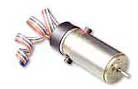 is
the standard motor part number used with most servo stages produced by Lick
Observatory for the Keck telescopes. IMPORTANT!
The new Galil motors have a different encoder with different wiring! THESE
NEW MOTORS ARE NOT COMPATIBLE WITH OLDER INSTRUMENTS. They have
an obviously different encoder housing but they have the same 10-pin ribbon
cable and IDC connector as the older style. The new style encoder now puts
out differential signals and are capable of driving the longer cables. The
motor specs, however, remain the same. Also important to note; the ribbon cable on the encoder has been modified to allow for a MOTOR_ENCD_CONN signal. In this case, the modification ties the unused pin 4 to the GND signal in pin 3. This signal is sent back to the control electronics and provides positive assurance that the motor encoder is connected.
is
the standard motor part number used with most servo stages produced by Lick
Observatory for the Keck telescopes. IMPORTANT!
The new Galil motors have a different encoder with different wiring! THESE
NEW MOTORS ARE NOT COMPATIBLE WITH OLDER INSTRUMENTS. They have
an obviously different encoder housing but they have the same 10-pin ribbon
cable and IDC connector as the older style. The new style encoder now puts
out differential signals and are capable of driving the longer cables. The
motor specs, however, remain the same. Also important to note; the ribbon cable on the encoder has been modified to allow for a MOTOR_ENCD_CONN signal. In this case, the modification ties the unused pin 4 to the GND signal in pin 3. This signal is sent back to the control electronics and provides positive assurance that the motor encoder is connected.
The Agilent HEDS-5540 secondary encoder and line driver The Agilent HEDS-5540 encoder is a 500 counts per revolution encoder. It is used as a load encoder and is attached to the ball screw that moves the ADC prisms. The HEDK-5540#A06 line driver module produces differential drive signals for the A, B and Index channels. The signals are fed back to the Galil motion controller to verify movement of the stage. The motor encoder is used for velocity and position information but the load encoder verify that the coupling is transferring the motion to the system. Note: as above, the ribbon cable on the encoder has been modified to allow for a LOAD_ENCD_CONN signal. In this case, the modification ties the unused pin 1 to the GND signal in pin 3. This signal is sent back to the control electronics and provides positive assurance that the load encoder is connected.
The Limit Interlock Panel
The interlock panel is mounted as a unit into the ADC electronics
box. The panel provides mounting area for the interlock components. This
includes the connectors that distribute all of the signals associated with
the interlock, the input connectors for the E-Stop, the local Manual
Paddle, the Bypass mode switch, and the error
indicator LEDs. The panel also provides the mounting for the interlock relays
and the +15V Bypass power supply. In essence, the interlocks prevent
stage movement when an error condition is encountered. It also provides local
control of the stage via the Manual Paddle. Please see the circuit
description for a detailed discussion of the functions performed by the
interlock system.
This page is meant mainly as a reference for the connections between the observatory and electronics box, and the electronics box and the interconnect panel at the ADC mechanism. The table at the bottom, left corner of the sheet gives the part numbers for the connectors used at these locations. For the most part, each of the connectors is a bayonet style MS connector. The exception is the network jack J102. This is a ruggedized RJ45 connector that allows compatibility with any normal CAT5 RJ45 connector. These connectors are actually a shell that snaps onto a RJ45 connector that holds the cable end inside a bayonet connector shell. This provides a secure mechanical connection using a common CAT5 cable. On the left side of the drawing, are the various input cables for the system. They include the AC power cable, the network connection, the observatory E-Stop input, and the manual paddle connector. Note: the dotted line for the manual paddle shows that the manual paddle can either be plugged directly into the electronics cabinet, or, the extension cable can be plugged in to allow use of the manual paddle at the instrument. The center of the drawing shows the cabling between the electronics cabinet and the instrument. The box labeled 'ADC STRUCTURE' shows the connections from the electronics box and to the various instrument functions. The table was of most used during the building of the instrument.
This page is meant as a reference for the main wiring within the electronics chassis and the stage interconnect panel at the instrument. Note that the motor power wiring is wired straight from the interlock panel to the motor. On the other hand, the logic signal wiring interconnects all of the different modules within the electronics box with the various stage connectors. The LOCAL/REMOTE wiring is also wired straight through to the instrument's manual paddle connector. Besides the motor and manual paddle wiring, a quick run down of the signals:
J406: Signals connected to interlock functions - stage limits and emergency stop signal. See pin out here
J405: I/O signals - NET/HARD error, emergency stop, motor and manual paddle connection signals, E-Stop input, LOCAL/REMOTE signal and BYPASS MODE signal. See pin out here
J405: Galil control signals - forward and reverse limits and HOME signal. See pin out hereJ403: Motor power in to interlock panel. See pin out here
J302: Logic signals - stage encoders, forward and aft cell limits and HOME signals, emergency stop, and cable connection signals. See pin out here.