This section contains descriptions of the stage interlock system for the ADC project. It corresponds to the 'Limit Interlock' tab in the schematics binder.
Interlocks, EL-3612
| Overall wiring | ||
| Manual Paddle wiring details | ||
| Limit switch wiring details | ||
| Motor wiring details | ||
| LOCAL/REMOTE wiring details | ||
| Bypass switch, reset switch, emergency stop, E-Stop, and bypass power supply wiring | ||
| Galil I/O wiring and LED Driver board wiring | ||
| Relay coil and contact wiring table |
Schematic: schematics\ADC_interlock.sch.pdf
Page last updated:
12-Mar-2007
Introduction:
The purpose of the interlock system is to keep the ADC instrument safe. For the control electronics this is accomplished by determining a set of specifications for the operation of the instrument, setting constraints for the moving prisms, and determining what types of failures might occur and how they might be dealt with. The following are the set of motions expected for the instrument:
The motion of the prisms are constrained by the following factors:
It is hard to predict what types of failures might occur with a system such as this. To help monitor the health of the mechanical system, extra sensors have been added to the instrument. To help diagnose a problem with the movement of the prism cells, a low resolution encoder has been added to the end of the ball screw of the forward cell. This might help catch something like a broken drive belt. To verify that both cells are tracking correctly an extra set of limits have added. These are located on the aft cell and are adjusted to trip at the same point as the secondary limits on the forward cell. If these limits don't agree the error will be flagged. In addition to the secondary limits there is also a HOME Hall-effect sensor on the aft prism cell. Again, this is used to help the software determine the health of the system.
The ADC has three separate modes of operation. They are:
The following set of diagrams illustrate these modes:
Normal computer operation:
This is the normal mode of operation. Looking at the diagram below, you see that the motor drive signals are wired to one set of normally closed contacts each on the LOCAL relay. As the diagram shows, the + contact on the motor receives its signal only if the LOCAL, 2DPL, or deploy secondary limit, and the BP, or bypass, relays are de-energized. The - motor contact receives its signal only if the LOCAL, BYPASS, 2RET, EMERGENCY STOP, and E-STOP relays are de-energized. On the diagram, notice too that the stage secondary limit's power, V_LIMIT, is connected to the GALIL controller's +5V power supply via a normally closed contact on the BYPASS relay.
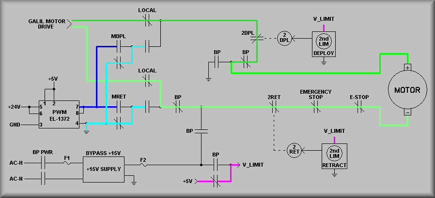
ADC Normal operation
Manual Paddle Deploy Motion:
The diagram below illustrates the use of the manual paddle to deploy the prism cells. (Deploy means to move both prism cells toward the ends of the instrument and away from each other.) The first thing to notice is that the LOCAL relay is now energized. This disconnects the Galil control system and connects the local PWM signal to the motor. By pushing the 'DEPLOY' button on the manual paddle the output of the Pulse Width Modulator card is fed to the LOCAL relay and through a now closed contact, to the 2DPL and BYPASS relays and on to the motor. A GND is also fed through a normally closed contact of the manual retract relay and through a now closed contact of the LOCAL relay contact and to the BYPASS, 2RET, EMERGENCY STOP, and E-STOP relays and on to the motor's - contact. These two signals cause the motor to move in the forward, or deploy, direction. Again, notice that the stage secondary limit's power, V_LIMIT, is connected to the GALIL controller's +5V power supply via a normally closed contact on the BYPASS relay.
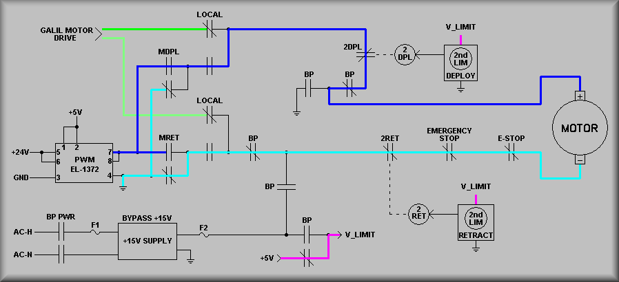
ADC Manual paddle deploy operation
Manual Paddle Retract Motion:
The diagram below illustrates the use of the manual paddle to retract the prism cells. (Retract means to move both prism cells toward each other to the center of the instrument.) The first thing to notice is that the LOCAL relay is now energized. This disconnects the Galil control system and connects the local PWM signal to the motor. By pushing the 'RETRACT' button on the manual paddle the output of the Pulse Width Modulator card is fed to the LOCAL relay and through a now closed contact, to the BYPASS, 2RET, EMERGENCY STOP, and E-STOP relays and on to the motor. A GND is also fed through a normally closed contact of the manual retract relay and through a now closed contact of the LOCAL relay contact and to the 2DPL and BYPASS relays and on to the motor's + contact. These two signals cause the motor to move in the reverse, or retract, direction. Again, notice that the stage secondary limit's power, V_LIMIT, is connected to the GALIL controller's +5V power supply via a normally closed contact on the BYPASS relay.
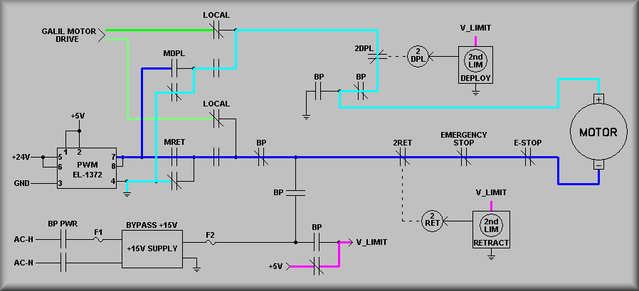
ADC Manual paddle retract operation
Bypass Mode Motion:
The diagram below illustrates the use of the bypass mode of operation. This condition is considered a severe failure of the control system. It is meant to provide a means of moving the prisms to the null position IF it is safe to do so. The system is put into bypass mode by manually changing the bypass switch from from 'Normal' to 'BYPASS'. This action will energize the BP, BP PWR, and BP CTRL relays. BP stands for BYPASS, BP PWR stands for Bypass Power and BP CTRL stands for Bypass Control. The BP relay disconnects the normal mode and manual mode power at the BP contacts. The BP PWR relay energizes the bypass +15V power supply. Notice near the top of the drawing that the BP contact ties the '+' contact of the stage motor to GND. Now, the +15V is applied to the 2RET, EMERGENCY STOP, and E-STOP relays. If these relays are in normal mode, the +15V is applied to the '-' contact of the motor and the prism cells will run to the Null point at the 2RET limit. Notice now that the stage secondary limit's power, V_LIMIT, is connected to the bypass power supply via the normally open contact on the BYPASS relay.
INPORTANT:
Once the instrument is at the Null point, the system will need manual intervention. First, the dome crew must troubleshoot and repair the cause of the problem that prompted the user to move the switch. Next, the cells need to be manually moved out of the retract secondary limit. The bypass switch needs to be returned to the 'Normal' position. Finally, the green 'Reset' button must be pushed on the electronics box.
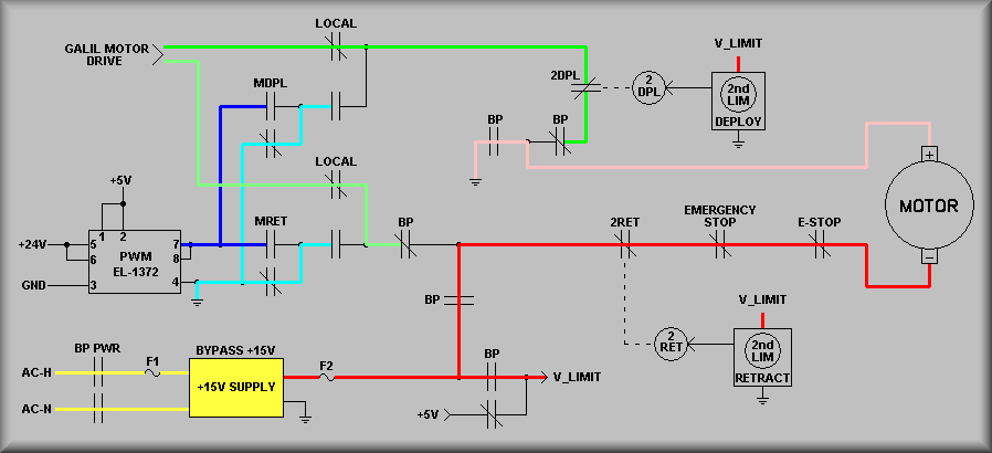
ADC Bypass mode retract operation
Sheet 1 attempts to give an overall, quick view of the function of the interlock system. At the top left corner is the motor signal from the Galil amplifier. These lines are connected to the normally closed contacts of the 'LOCAL' relay RLY7. Assuming that the system is not in the local mode, the top motor line is wired to a set of normally closed contacts on the deploy secondary limit relay, RLY12. Now the line is wired to the bypass relay, RLY1 and on to the motor '+' terminal. The lower motor signal is wired from the local relay contact to a set of normally closed contacts on the bypass relay, RLY1, to the retract secondary limit relay, RLY11, on to normally closed contacts on the emergency stop relay,RLY4, next to normally closed contacts on the E-Stop relay, RLY10 and then on to the '-' terminal of the motor.
Looking at the manual paddle in the lower right portion of the diagram, if the manual paddle is plugged in and the toggle switch is selected for 'local' control, the local relay at the upper left of the drawing will pull in. This will disconnect the Galil motor signal and enable the signals from the MDPL, manual deploy relay, and MRET, manual retract relay. These signals include the Pulse Width Modulated (PWM) signal and a GND. If the 'Deploy' button on the manual paddle is pushed, the PWM signal is passed to the local relay contact that is now closed. From here it goes to the deploy secondary contacts and the bypass relay contacts and to the motor. Meanwhile, the GND is connected through the normally closed contacts of the MRET relay, to the now closed contact of the local relay, the bypass, 2RET, emergency stop, and E-Stop relay contacts and on to the motor. If the 'Retract' button on the manual paddle is pushed, the PWM signal is passed through the MRET contact and on to the local relay contact that is now closed. From here it goes to the bypass, 2RET, emergency stop, and E-Stop relay contacts and on to the '-' terminal on the motor. Meanwhile, the GND is connected through the normally closed contacts of the MDPL relay
to the deploy secondary contacts and the bypass relay contacts and to the motor.
At the bottom left of the drawing are the bypass relays. The first is the BP CTRL, or bypass control, relay. Its job is to energize the BP, or bypass relay, and the BP PWR, or bypass power relay. Once the bypass system switch is actuated, the BP CTRL relay energizes. A set of normally open contacts on the BP CTRL relay then pull in and latches the relay on. At this point, the 15V bypass power supply turned on. Meanwhile, the BP contacts are now toggled and both the Galil and manual control signals are cut off from the motor. In the upper, center of the drawing, the BP contact now feeds a GND to the '+' terminal on the stage motor. Also the +15V line is connected to the motor '-' terminal via the 2RET, emergency stop, and E-Stop relay contacts. The system will now run the prisms to the null position. Remember that the BP CTRL relay is latched on. On the lower left side of the diagram is the 'Front Panel Reset Switch'. To get back out of the bypass mode, this switch must be pushed to release the relay. IMPORTANT: you MUST repair whatever caused the use of the bypass mode before returning the system to operation. Failure to do so may cause severe damage to the system.
To the right of the BP PWR relay on the drawing is the emergency stop system for the instrument. The two switches are wired in parallel so that either can energize the stop relay (RLY4). One switch is located on the front panel of the electronics box and the other is located at the instrument. Notice that besides that two switches the E-Stop contacts will also energize the stop system. As with the bypass system, the emergency stop system will require that the operator manually depress the reset button to restore operation of the system. Again, you MUST repair whatever caused the use of the emergency stop mode before returning the system to operation. Failure to do so may cause severe damage to the system.
The square symbols in the center of the drawing and to the right edge represent the Hall-effect limit sensors. Each of these signals is wired to a transistor driver circuit to actuate the relay associated with the limit.
This sheet shows the the wiring for the manual paddle. The +24V power line is wired from Pin A to one pole of the SPDT LOCAL/REMOTE switch. When the switch is set to remote, or computer control the +24V is disconnected from the direction pushbuttons. At that same time the LOCAL/REMOTE signal is tied to ground via the second pole of the switch. This line is wired to one side of the relay coil of RLY7, the LOCAL relay,and the other side of the coil is wired to GND. thus, the relay is not energized. Also at this time, the normally closed pole of both direction switches are tied to GND. Because the normally open poles of the direction switches are also wired to GND, there can be no energizing of either direction relay. (On the interlock panel these are relays MDPL and MRET - for manual deploy and manual retract).
When the switch is moved to the LOCAL position, Pin G is connected to +24V which pulls in the LOCAL relay in. It also connects the normally closed contacts of the direction switches to +24V. Now with the +24V available to either switch, pushing either switch will pull in the appropriate direction relay. A direction interlock is achieved by wiring the GND for each relay through the normally closed contact of the opposite direction switch. Thus, if you push and hold one direction button and then push the other, the GND signal is removed from both direction relays. As shown on the left side of the diagram, the 24V signal for each of the manual direction relays is wired through its corresponding primary limit. Remember, in the manual mode, the Galil motor signals are disconnected from the motor. Thus, even though the Galil will see the primary limits, stopping the motor signal has no effect on the actual motor that is connected to the manual system.
NOTE: this sheet shows simplified wiring for the Hall-effect sensors. There is an intermeadiate cable between the sensors and J604 that has been left out. For details, see EL-3610 sheet 5.
This sheet details the wiring of the forward prism cell limit sensors. Each of the sensors used on this instrument is a Cherry VN101501 Hall-effect vane switch. At the top left corner of the drawing is the input from the HOME sensor on J406 Pin 7. Unlike the rest of the sensors on this sheet, the HOME signal is fed directly to the Galil controller via the AMP-19520 amplifier module. Also note that the supply voltage for the sensors is wired to Pin 4 of J406. This signal is derived from the bypass relay and is +5V in either normal or manual control modes but +15V in bypass mode. (This isolates the Galil system entirely in case it is the problem).
For the rest of the sensors, notice that the sensor outputs are wired into the interlock panel and then to the EL-3603 Relay Driver board. The signals turn on a 2N4403, PNP transistor which in turn drives the associated control relay. The deploy primary limit is wired via Pin D of J604 to Pin U of J502 and J302, and on to Pin 4 of J3 on the relay driver board. The deploy secondary limit is simularly wired to J3 Pin 1.
This sheet details the main motor wiring. At the top of the sheet is the motor cable connected signal wiring. As can be seen, a GND is wired from the interlock panel to Pin C of J404, the 5 pin motor connector. This GND arrives at the final motor connector, J601 pin C where it is connected back to pin B where it becomes the MOTOR_CONN signal. This signal wires back to the interlock panel via J501, J301, and J404. Next it is routed through J402 and then back to the Galil I/O panel. Obviously, if any of the motor connector are disconnected the I/O bit will go high. What's not so obvious is that this signal does not pass through the molex connector of the actual Galil amplifier. So this becomes an ambiguous state and should be kept in mind when troubleshooting.
The rest of the diagram shows the motor wiring. At the left, the Galil motor signals MOT1 and MOT2 come in to the 2DPL (deploy secondary limit) and the BP (bypass) contacts respectively. The relay contacts show all of the conditions that must be met before the motor can be operated. For MOT1, the 2DPL and BP relays must not be energized. For the MOT2 signal, the BP, 2RET, STOP, and E-Stop relays must also not be energized. This also points out the limits that are still in the system even in manual and bypass mode. MOT1 is wired to Pin A on J404, J301, J501 and J601. Mot2 is similarly wired to Pin B.
This sheet shows the wiring details for the manual motion relays. The bottom third of the schematic shows the wiring details for the Local relay. The Local/Remote switch is wired so that when the switch is in the 'Local' position, the +24V is applied to the Local relay. This signal is wired to Pin G of the manual paddle, J606, JJ503, J303, and J202. Simularly, +24V is wired to Pin A and GND is wired to Pin H.
At the top of the drawing, notice that the upper most set of contacts on the Local relay are wired so that when the relay is energized the LOCAL/REMOTE signal will go high and the signal to the front panel indicator will pull dowm to GND. In the case of the LOCAL/REMOTE signal, the pull-up resistor on the Galil I/O module will pull this signal hight and in the case of the LED, the GND signal will illuminate the LED. The LOCAL/REMOTE signal is wired to J405 Pin 15 and is wired back to I/O bit 67. On the Local relay, the lower two sets of contacts are wired to select between the Galil motor signal and the manual paddle relays. Here, if the manual paddle is selected for remote operation, the MOT1 and MOT2 signals are passes through to the rest of the interlocks. The signals come into the interlock panel on J403 Pins A and B.
When the Local/Remote switch on the manual paddle is set to local operation, the two lower sets of contacts on the Local relay pass the PWM +24V signal and GND on to the rest of the interlocks. First, assume that neither direction button is pushed on the paddle. The two lower normally closed sets of contact on the motion relays, MDPL and MRET, will pass on GNDs to both sides of the motor. Now, when the Deploy button is pushed, the MDPL relay pulls in. With the relay energized, the connection to GND is broken and the +24V is fed to the motor via the middle set of contacts of the Local relay and the GND remains on the lower set causing the motor to run in the deploy direction. Alternately, pushing the Retract button causes the +24V to be connected to the lower set of contaqcts on the Local relay and the GND to be on the middle set of contacts. This will run the motor to run in the retract direction. One would think that then if you pushed both buttons that +24V would be sent to both sides of the motor but this mode is not possible because the pushbuttons themselves are interlocked and both relays drop out if the second button is pushed at the same time.
This sheet gives wiring details for the Bypass mode and emergency stop system. At the top left of the diagram are the Front Panel Reset Switch and the Bypass Mode Switch. Notice that the Front Panel Reset Switch has two sections. The bypass mode section and the emergency stop section. This illustrates that both systems are reset via the one pushbutton. This button lives on the front panel of the electronics box and must be depressed manually.
The Bypass Mode Switch is also mounted on the front panel of the electronics box. It too requires an operator to change it manually. This is because if it is needed the operator should be at the box examining the status of the LEDs. Again, this is a last ditch solution to attempt to move the prism cells into the Null position.
The Bypass Mode Switch provides a GND to the 'B' side of the relay coil. The +24V is supplied via the Reset Switch. When the Bypass Mode Switch is actuated the bypass control relay pulls in. Notice that one of the contacts of the bypass control relay is wired to GND in parallel with the Bypass Mode Switch. This latches the relay and means that flipping the bypass switch back to normal will not interrupt the bypass mode. On the top, right portion of the diagram are the Bypass and Bypass Power relays. The 'A' side of the relay coils are wires to +24V. When the bypass control relay pulls in, a GND is supplied to these relays' 'B' side via a contact on the bypass control relay. The bypass relay directs the flow of current to the motor and the bypass power relay supplies 120VAC to the +15V bypass supply which is detailed at the bottom of the diagram. Notice at the bottom of the diagram that one set of contacts on the bypass relay substitutes the bypass +15V for the normal +5V supply for the forward prism cell's limit sensors.
The emergency stop relay is located in the center of the drawing. To the left of it are the two emergency stop pushbuttons. The topmost of the two is located at the electronics interconnect box on the instrument and is wired via the main logic cable on Pins L and M. The lower switch is mounted on the front of the electronics cabinet on the interlock front panel. These switches are wired in parallel so that tripping either one will cause the instrument to stop. Notice also that a set of contacts on the stop relay, as well as a set of the E-Stop relay contacts, are wired also wired in parallel. Thus, if either of the emergency stop buttons are pushed or the observatory E-Stop is actuated, the stop relay will pull in and will not be released until the reset pushbutton is actuated.
The E-Stop relay is shown in the right side middle of the diagram. This is a 120VAC relay that is wired to the Keck specified connector per their instructions. This relay is energized during normal operation and relaxes if an E-Stop condition exists. The motor signal is directly interrupted by a set of contacts on the E-Stop relay.
This sheet shows all of the instrument interlock status bit wiring. First, looking at the left side of the drawing, the status bits going to the Galil IOM-1964 I/O module are detailed. Except for the HOME signal, each input to the I/O module is derived from a normally closed set of contacts on the various relays. The pin numbers and signal names on the left side of the page spell out the wiring for each signal. The right half of the page shows the wiring for the EL-3604 LED Driver board. This board is mounted directly to the front panel of the interlock panel. Other then for the NET/HARDWARE ERROR circuit and the bypass circuit, each LED is wired to a set of relay contacts. When that relay is actuated the appropriate LED will illuminate. In the case of the bypass system, the +15V power supply is wired to it's LED inticator directly. For the NET/HARDWARE ERROR circuit, a 'deadman' circuit illuminates the LED if the pulses from the controller go away. (See the EL-3604 write-up for details.)
The last sheet of the interlock schematics is a wire list for the 12 relays in the interlock system. These tables won't be reproduced here. The tables are set up with the first colomn denoting the pin on the relay/socket. The second column shows the function of the pin, i.e. a coil conntction or contact connection. The 'FROM' column details where the signal came from and the 'TO' column shows where the wire continues to if appropriate. The 'SIGNAL' column refers to the of the signal as used in this documentation. The last column calls out the sheets of the interlock schematic that shows that contact.