APF Spectrograph Electronics
Automated Planet Finder Calibration Lamp Stage,  EL-3514
Schematic: schematics\APF_calib_lamp_sh_1.pdf
Page last updated: January 30, 2012
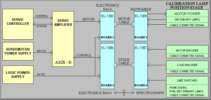
Simplified Diagram- Refer to first page of schematic for more details
The APF Calibration Lamp stage selects from one of five light sources, three of which are currently defined. The light sources are:
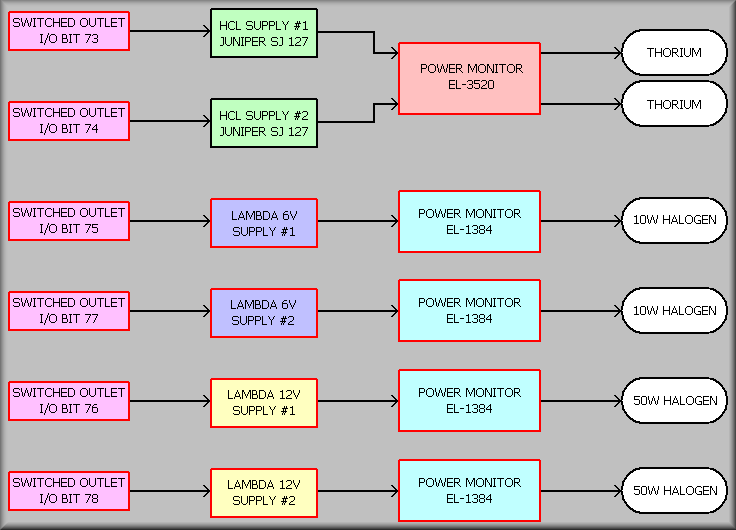
- Primary Thorium - this is a single thorium lamp, filled with a mixture of 90% neon and 10% argon. The lamp is driven by a dedicated Juniper model SJ 127 power supply, and will be either fully on or fully off. Galil output bit 17 will turn the lamp's power supply on and off, and input bit 73 indicates if current is flowing through the lamp. The current is monitored by the APF Hollow Cathode Lamp Current Monitor Board EL-3520.
- Secondary Thorium (hot backup) - used if primary lamp fails. The lamp is driven by its own Juniper model SJ 127 power supply. Galil output bit 18 will turn the lamp on and off, and input bit 74 indicates if current is flowing through the lamp.
- Integrating Sphere - contains two pairs of filtered halogen light sources, 10 watt and 50 watt, operated in unison or independently. There is an additional pair of halogen lamps, serving as hot backups. The primary 10 watt halogen lamp is controlled via output bit 19 and monitored via input bit 75. The primary 50 watt halogen lamp is controlled via output bit 20 and monitored via input bit 76. The secondary 10 watt halogen lamp is controlled via output bit 21 and monitored via input bit 77. The secondary 50 watt halogen lamp is controlled via output bit 22 and monitored via input bit 78. These current through these lamps are monitored via EL-1384 boards.
The lamps are attached to a standard THK linear stage. The stage is connected through a bellows-style coupler to an Magmotor Corporation SR15-O-200X, Rev. A DC servo motor. The motor has a US Digital model E6MD-2000-197-E encoder coupled directly to the shaft and is noted as the 'motor' encoder on the schematic. The load encoder is a Turck Kubler type T8.L2.122.1122.0005 magnetic read head with K180520 magnetic tape. The load encoder read head is mounted to the base of the stage and the tape is adhered to the bottom of the moving portion of the stage. A UCO/Lick EL-1393 Triple Hall-Effect Limit board is also mounted base of the THK stage. The board contains sensors for the forward and reverse limits and the home sensor. Flags mounted to opposite ends of the moving stage that actuate the sensors. When moving in the forward direction, the flag on the end of the stage closest to the motor trips the forward limit at the end of travel. When moving in the negative direction the flag on the end of the moving stage furthest away from the motor will trip the reverse limit. The home sensor is located close to the reverse limit. This allows use to use one flag for both functions. A DT-2RV22-A7 DPDT limit switch is mounted near the limit sensor board. The moving portion of the stage has a notch cut out at its forward end. This notch is machined precisely to coincide with the secondary limit for reverse travel. The opposite end of the plate is machined precisely to coincide with the forward secondary limit. This allows the use of only one micro switch to signal either secondary limit. The second set of contacts on the DPDT switch are wired to the controller to indicate that the switch has been tripped. Notice that on each of the green boxes above that there is a CABLE CONNECTED signal. These signals are wired to I/O bits. When any one of the cables is disconnected the software will flag it and ask to have the condition of that cable examined.
Sheet 2  APF_calib_lamp_sh_2.pdf
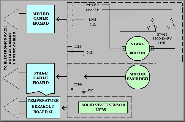
Simplified Diagram - Refer to second page of schematic for more details
The second sheet of the schematic shows the wiring of the stage motor, the motor encoder, the secondary limits, and the motor temperature sensor. At the left side of the schematic are the motor power breakout board, the stage breakout board, and the temperature breakout board. The motor and stage boards are Lick LOEL boards while the temperature breakout board is a Winford Eng. generic DB-25 board.
The motor breakout board, J5, is the first of two such boards used by the APF spectrograph. The 6-pin connector supplies the power to the servo motor, returns the secondary limit signal, CAL_SEC_LIM, and the cable connected signal, CAL_MOT_CONN, back to the Galil controller. The signal names on the first three pins reflect an early scheme to use brushless DC motors which were dumped due to the Galil's trapezoidal commutation operation lacking the ability to position as reliably as needed. Thus, the Phase_3 signal has been abandoned and the Phase_1 and Phase_2 are now used for the two regular DC motor leads. In a break from the past, the APF secondary limit uses just the one limit switch which goes active when the roller falls off either end of the limit actuator. The important thing is that if the secondary is tripped, the power to the motor is disconnected and the secondary limit signal goes high. Finally, the GND signal from the controller is looped back to the input bit 60 as the cable connected signal. The motor for this stage, as all stages, is a Magmotor P/N 50015060 while the Model is SR15-O-250X. The connections to the motor are made via a AMP MATE-N-LOK connector detailed at the bottom, right hand side of the schematic.
At the left middle of the schematic, J2 is located on the stage breakout board for the Calibration Lamp stage. This connector connects to the motor encoder. The motor encoder is a US Digital E6MD-2000-197-E. As per the note beneath the encoder, the A and B channel wiring is swapped to make the motion consistent for all motor and load encoders. In all cases, moving the stage in the forward direction moves the shuttle away from the motor and moving in the reverse direction move the shuttle toward the motor. Notice that pins J2-8 and J2-9, the Index+ and Index- signals are not used. The APF motion controller use the index signal from the load encoder to establish the zero point of the stage. The US Digital encoders provide differential A and B channel signals for better noise immunity. Lastly, the encoder connected signal is wired to pin J2-2. You'll note that this signal is not derived from within the encoder but rather on the plug that is connected to J2. Thus, if the the cable is disconnected at the actual encoder the cable connected signal will remain low even with the encoder disconnected.
The bottom left block represents the Winford Engineering DB-25 breakout board. This COTS board breaks out the twenty five conductors to twenty nine screw terminals. (Pin 25 is repeated with each of three blocks of eight terminals - see here for the Winford drawing). Each stage motor has a solid-state temperature sensor, LM35, strapped to its body. These are provided as a means for tracking down unexplained heat generation within the spectrograph.
Sheet 3 APF_calib_lamp_sh_3.pdf
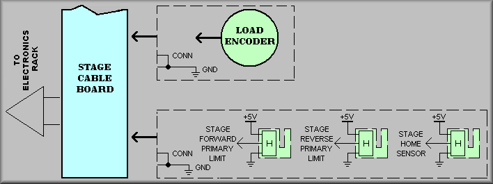
Simplified Diagram - Refer to third page of schematic for more details
The third sheet of the schematic shows the rest of the EL-1399 stage breakout board. At the top are the connections for the stage's load encoder and at the bottom are the primary limit switches and home sensors. The Turck Kubler magnetic read head linear encoder is connected to J4 and the Lick EL-3593 Stage Limit board is connected to J3. Notice that the load encoder's index signals are wired back to the Galil controller. Also, the CAL_LOAD_ENCD_CONN signal is wired to J4-8 and then on to input bit 58. At J3, the CAL_LIMIT_CONN signal is wired to pin 9 and then on to input bit 57.
Sheet 4 APF_calib_lamp_sh_4.pdf
Simplified Diagram - Refer to fourth page of schematic for more details