APF Spectrograph Electronics
Automated Planet Finder ADC Stage,  EL-3511
Schematic: schematics\APF_adc_sh_1.pdf
Page last updated: January 9, 2012
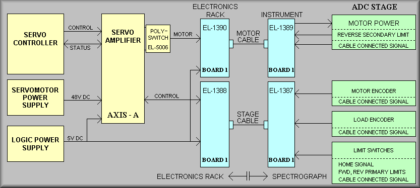
Simplified Diagram - Refer to first page of schematic for more details
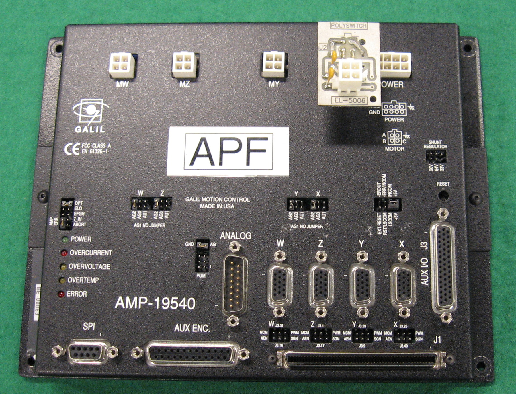
The APF Atmospheric Dispersion Corrector (ADC) stage optically consists of a set of two prisms. One prism is fixed and the other moves either toward or away from it. From a control standpoint, the stage consists of a motorized stage, encoders, a HOME sensor, and limit switches. In the above drawing, the control system is shown on the left and the stage is on the right. At the heart of the control system is a Galil Motion Control DMC-2280 controller. In concert with the Galil AMP-15940 servo amplifier, the controller provide precise motion control for each of the APF stages. The Kepco 48V power supply provides power to run the motors and the Kepco 5V power supply provides power for controller I/O. Note: Quick Start and Operator manual links for the Kepco supplies can be found on the APF Documents web page and complete manuals are available at the APF dome. In the center of the above diagram, the blue blocks represent the various breakout boards built especially for the APF spectrograph electronics. These boards combine stage signals and power from various points in the electronics rack to feed the stage cable and motor cable and then break them back out for easy connection to elements of the stage within the spectrograph. The right side of the drawing shows the stage elements. Unlike the six other stages of the spectrograph, the ADC has only a reverse secondary limit. Due to the need to move the two prisms as close as possible to null them, there is no room for a forward secondary limit. To be clear, the forward limit of travel is where the two prisms nearly touch. In case of a failure of the primary and software limits, a Raychem 1.6A Polyswitch re-settable fuse , photo 13 below, is used to remove current from the motor. The ultimate end of travel of the stage is were the moving portion hits the end of the nonmoving end of the stage. At this point, the prisms are still separated but if allowed, the motor would draw more and more current. The re-settable fuse will heat up and disconnect the motor from the circuit. To reset the fuse power needs to be removed from the circuit. This is the only case in the APF spectrograph where a secondary limit does not report back to the software that the condition exists.
Sheet 2  APF_adc_sh_2.pdf
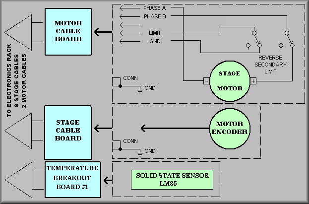
Simplified Diagram - Refer to second page of schematic for more details
Please refer to photos 1 and 2 below to understand the relationship between various stage components. However, remember that the ADC stage has a slightly different secondary limit switch mounting scheme. The moving prism is attached to a standard THK linear stage. The stage is connected through a bellows-style coupler to a Magmotor Corporation SR15-O-200X, Rev. A DC servo motor. The motor has a US Digital model E6MD-2000-197-E encoder coupled directly to the shaft that is noted as the 'motor' encoder on the schematic.
In the above drawing, the top green circle represents the stage motor. Note that the secondary limit DPDT switch has one circuit wired in line with one pole of the motor. This is wired to the normally open (N.O.) section of the switch. In operation, the roller is depressed until the stage reaches the physical end of travel (see photo 1 below). The second circuit of the secondary limit switch provides a ground to the stage's secondary limit general input signal. The green circle in the middle of the drawing represents the motor encoder. The encoder provides A and B channel quadrature signals to the controller. These signals are connected to the auxiliary encoder inputs because the system is using the dual encoding scheme. In this scheme the motor encoder is used for velocity information and a second 'load' encoder is used for position information.
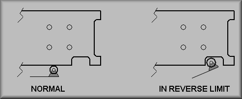
ADC Secondary Limit Actuation
The above drawing is provided to show the operation of the ADC's reverse secondary switch. A Honeywell DT-2RV22-A7 DPDT limit switch is mounted near the limit and HOME sensor board. The moving portion of the stage has a notch cut out at its forward end. This notch is machined precisely to coincide with the secondary limit for reverse travel. While all other stages have a forward secondary limit, the ADC stage is built such that a forward switch is impractical. This is due to the need to move the prisms as close as possible to achieve a "Null" position - one where the light passing through the ADC is essentially unaffected by the prisms. This coupled with the large hysteresis makes a physical switch incapable of filling our requirements. Instead, we have added a thermal, re-settable fuse, or Polyswitch, from Raychem. This device essentially opens when the motor current exceeds about 3 amperes, as it would if the stage hit its hard stop. Once the device has "opened", the software must remove power from the motor in order to "reset" the device - thus the term "re-settable fuse". Unfortunately, the use of the polyswitch device means that the hardware, and thus the control program, does not receive feedback when the stage does hit the hard limit. To work around this problem, the control program is required to monitor the stage encoders to verify ADC motion to determine if the stage is moving or in the forward limit. As for the reverse limit, the second set of contacts on the DPDT switch are wired to the controller to indicate that the switch has been tripped.
Sheet 3 APF_adc_sh_3.pdf
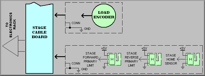
Simplified Diagram - Refer to third page of schematic for more details
On the ADC schematic, the load encoder is a Turck Kubler type T8.L2.122.1122.0005 magnetic read head with K180520 magnetic tape. The load encoder read head is mounted to the base of the stage and the tape is adhered to the bottom of the mounting plate that is attached to the moving portion of the THK stage. As seen in the above drawing, a UCO/Lick EL-1393 Triple Hall-Effect Limit board (see photo 12 below) board is also mountedto the base of the THK stage. The board contains sensors for the forward and reverse limits and the home sensor. There are flags mounted to opposite ends of the moving stage that actuate the sensors. When moving in the forward direction, the flag on the end of the stage closest to the motor trips the forward limit at the end of travel. When moving in the negative direction the flag on the end of the moving stage furthest away from the motor will trip the reverse limit. The home sensor is located close to the reverse limit. This allows use to use one flag for both the reverse limit and homing functions. Notice that on each of the green boxes above that there is a CABLE CONNECTED signal. These signals are wired to I/O bits. When any one of the cables is disconnected the software will flag it and ask to have the condition of that cable examined.
As is the case with all of the APF Spectrograph stages, the ADC stage has standardized wiring. The green circle represents the load encoder that is connected directly to the stage. The load encoder is a magnetic type in which the read head detects the magnetic pattern on a magnetic tape that is adhered to the moving portion of the stage. The load encoder is connected to the stage's main encoder input, again for the dual encoding scheme. The load encoder provides A and B channel quadrature signals plus an index pulse to the controller. The magnetic tape provides an index pulse every 2 mm. (0.078 in.) For the homing sequences, the normal find edge, find index sequence uses the next index pulse on the tape for zeroing out the position counters.
A UCO/Lick EL-1393 Triple Hall-Effect Limit board, photo 12 below, is also mounted base of the THK stage. The board contains sensors for the forward and reverse limits and the home sensor. There are flags mounted to opposite ends of the moving stage that actuate the sensors, photo 2. When moving in the forward direction, the flag on the end of the stage closest to the motor trips the forward limit at the end of travel. When moving in the negative direction the flag on the end of the moving stage furthest away from the motor will trip the reverse limit. The home sensor is located close to the reverse limit. This allows use to use one flag for both functions. While the forward and reverse primary limits are used to stop motion of the stage, there are also software limits that trip before reaching them. These were empirically determined during the building of the spectrograph and they are saved as operating parameters for the control system.
General stage photos:
Photo 1.
Standard APF spectrograph stage
Photo 2.
Limit component identification
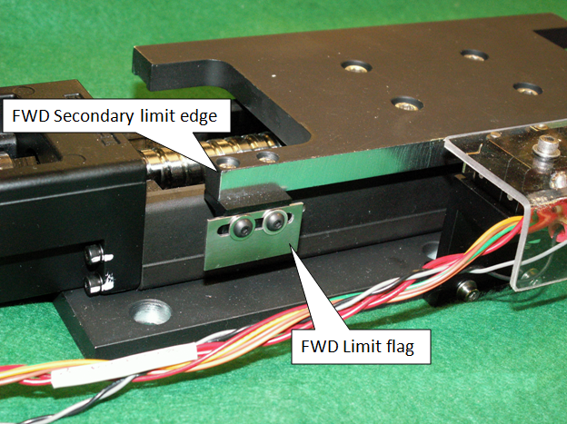
Photo 3.
Forward limit flag
Photo 4.
Forward travel limit sensor
Photo 5.
In forward travel limit
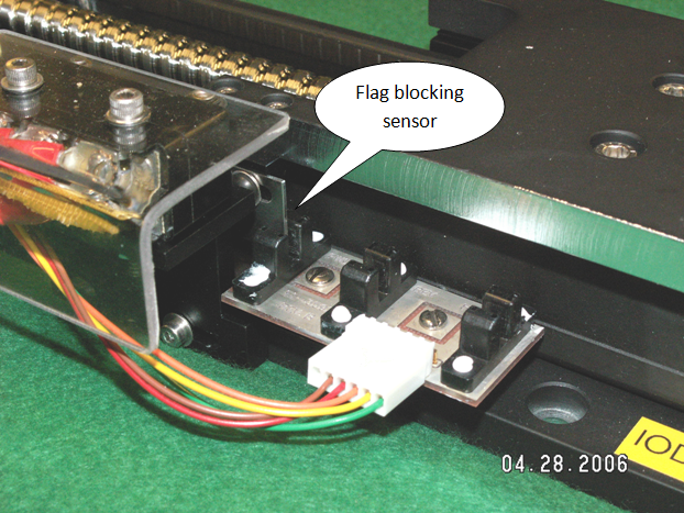
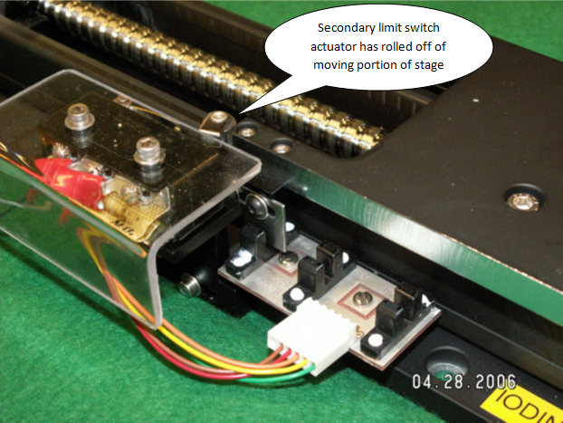
Photo 6.
In forward secondary limit-
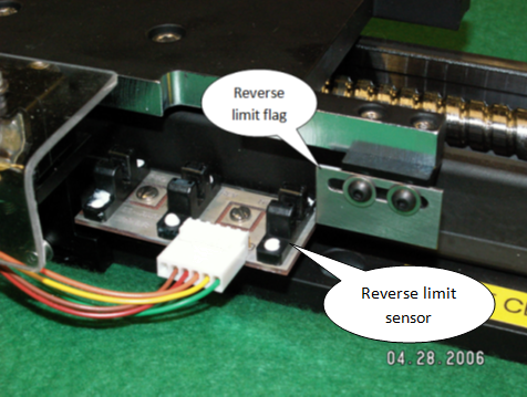
Photo 7.
Reverse primary limit 
Photo 8.
In reverse limit
Photo 9.
In reverse secondary limit-
Photo 10.
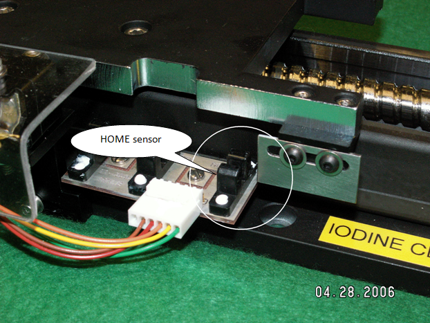
HOME sensor -
Photo 11.
In HOME sensor 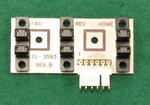
Photo 12.
EL-3593 Triple limit board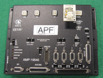
Photo 13.
Polyswitch board