Cradle Wiring
The cradle stage wiring section of this manual contains descriptions of the rotation stage wiring and associated systems for the cradle portion of the DEIMOS Spectrograph. It corresponds to the Cradle Stage Wiring tab in the electronics schematics binder.
Rotation Manual Paddle, ![]() EL-3141,
EL-3141, ![]() EL-3142
EL-3142
Schematic: schematics\MANCNTRL0.sch.pdf, deimos\MANWIRE0.sch.pdf
Page last updated:
February 20, 2003
Simplified Drawing
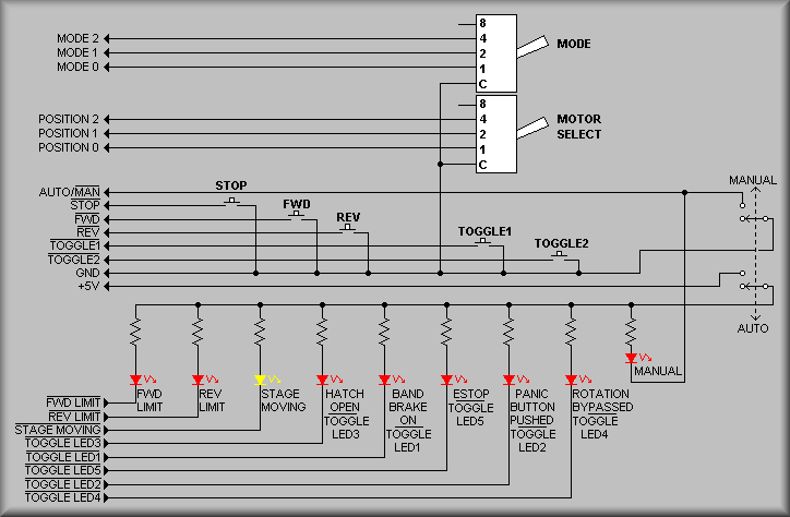
The above diagram shows the signals associated with the manual control paddle for the DEIMOS instrument rotation stage. (The paddle is shown pictorially below.) The paddle consists of two thumbwheel switches, three pushbutton switches, a toggle switch, and nine LEDs. The wiring to and from these elements terminate into a 24-pin MS style connector. The toggle switch shown at the right side of the drawing allows the user to enable the paddle for local control of the instrument rotation or disable it for computer control. One section of the DPDT switch connects one side of the pushbutton switches and the common terminal of the thumbwheel switches to ground. The other section applies +5 volts to each of the LEDs via a current limiting resistor. The two thumbwheel switches are shown at the top of the diagram. They allow the user to select the mode of operation of the paddle. These modes include:
The Fast Jog mode allows the user to rotate the instrument
in either the forward or reverse direction. The instrument will continue to
rotate as long as the pushbutton is held down. Once the user lets go of the
pushbutton the instrument will decelerate to a stop before accepting any further
direction information. This ensures that the instrument will not attempt to
reverse direction while moving. As with all paddle input, the instrument is
under full control of the various limits - software, primary, and secondary
hardware limits.
The Slow Jog mode allows the user to rotate the instrument
at a slow speed in either the forward or reverse direction. This mode would
normally be used for inspection or troubleshooting tasks.
The Position Switch mode move the rotating portion of the instrument
to an exact position as dictated by the setting of the Position Thumbwheel Switch.
Once selecting the Position Switch mode, pushing either the FWD or the REV pushbuttons
will initiate the move. See below for the discrete positions available.
The Next 90° Position mode will move the instrument to
the next 90° position angle. That is, 0°, 90°, 180°, etc. In
this mode, the direction of travel is determined by which pushbutton is pressed.
The Sound mode is not implemented in the electronics - the
software group will determine how to use this feature.
The Home mode will move the instrument to it's zero point and
reset it's position. The instrument must be 'homed' before it can be moved manually.
If the instrument has not been 'homed', the forward and reverse limit LEDs will
be blinking.
The Position Thumbwheel switch is used to select between several discrete positions. They are:
The -90° position will set the instrument in the 'standard'
position for storing or working on the instrument.
The Dewar Fill Right position rotates the instrument to the
position used to fill the CCD dewar from the right hand side of the instrument.
The Dewar Fill Left position rotates the instrument to the
position used to fill the CCD dewar from the left hand side of the instrument.
The Grating Access position moves the instrument into position
to allow the operator to change gratings.
The Slitmask Access position moves the instrument into position
to allow the operator to change slitmasks.
The Filter Access position moves the instrument into position
to allow the operator to change filters.
The Negative Limit position rotates the instrument to the negative
position angle software limit. This is a diagnostic position and should not
normally be used.
The Positive Limit position rotates the instrument to the positive
position angle software limit. This is also a diagnostic position and should
not normally be used.
The three pushbutton switches are:
The FWD pushbutton tells the rotation computer to initiate
a move in the forward direction. This increases the instrument's position angle.
The REV pushbutton tells the rotation computer to initiate
a move in the reverse direction. This decreases the instrument's position angle.
The STOP button is used to stop any movement initiated by the
paddle. WARING: This button will not stop computer
controlled movement or any abnormal movement. If the instrument 'runs away'
or it's movement creates an unsafe situation, USED THE RED PANIC BUTTONS on
the carriage to break connection to the motor.
The LEDs on the paddle give the operator status indications. These LEDs are
not enabled when the Computer/Manual in in the Computer position. The labels
on the LEDs describe the conditions they signal. The Forward and Reverse Limit
LEDs will turn on when a limit is encountered. (Also, if they both are blinking
at the same time, the rotation stage has not been homed.) The yellow Moving
LED tells if the the instrument is moving or not. In many cases, the instrument
may be moving too slowly to detect. In these cases the Moving LED tells the
operator when the stage is moving or stopped. The last five error/status LEDs
indicate the condition of the instrument.
Simplified Drawing
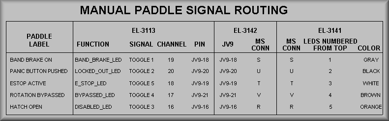
The above table is provided to help correlate the signal name, generic signal name, function, and wiring of the five status/error LEDs on the rotation hand paddle. Due to the long duration of construction and a desire to keep things standardized, the signal names and functions have seemingly been given random names, etc. The above table is used as a reference with the LEDs sorted as per their physical position on the paddle. (See the next to last column.)
![]() EL-3142
EL-3142
Simplified Drawing
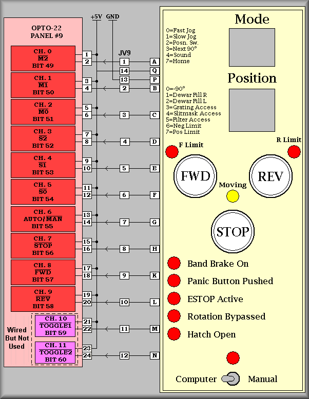
The above drawing shows the various inputs to the rotation computer from the manual paddle. Each signal above is located on the 24-pin MS connector at the designation to the immediate left of the paddle image. The signals wire to various intervening connectors but the pin designations stay the same until they reach the CPC connector JV9. Here, the designations change from letters to numbers due to the conventions used by the connector manufacturers. To follow the signal paths, the CPC connectors are then wired to terminal strips on the individual Opto-22 relay racks. Note that, again for compatibility, the signals for TOGGLE1 and TOGGLE2 have been wired but no relays have been installed into the relay rack.
Simplified Drawing
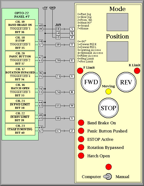
The above drawing shows the various outputs from the rotation computer to the manual paddle. Each signal above is located on the 24-pin MS connector at the designation to the immediate left of the paddle image. The signals wire to various intervening connectors but the pin designations stay the same until they reach the CPC connector JV9. Here, the designations change from letters to numbers due to the conventions used by the connector manufacturers. To follow the signal paths, the CPC connectors are then wired to terminal strips on the individual Opto-22 relay rack.