Barrel Electronics
Though the barrel electronics section of this manual contains
descriptions of the barrel electronics for the DEIMOS Spectrograph, this drawing
refers to the overall AC wiring of the entire instrument.
Main
AC Power Wiring,  EL-3002
Schematic: schematics/ACPWR.sch.pdf
Page last updated: June 25, 2002
Jump to: sheet 2, sheet 3, sheet
4, sheet 5, sheet 6, sheet
7
This
7 sheet schematic shows the AC power wiring for the DEIMOS instrument. The
first sheet gives a block diagram and a view of the overall interconnections
between the various components of the system. Sheet 2 gives the detailed wiring
schematic for the circuit breaker box. Sheets 3 and 4 show the layout of the
various electrical and electronic components on both the barrel and the cradle.
Sheet 5 gives connector and wiring details for the AC wiring. Sheet 6 gives
details of the wiring at the terminal strips inside of the circuit breaker
box and sheet 7 shows the connector layout on the circuit breaker box.
Sheet 1:
Simplified Drawing
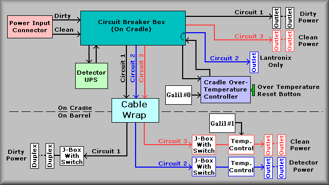
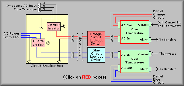
The above drawing shows the overall AC power wiring of the DEIMOS instrument
in block diagram form. The turquoise block is a representation of the circuit
breaker box located in bay B of the cradle portion of the instrument. Power
enters the instrument via a 7-pin MS-style connector at the rear of the instrument.
Pins A, B, and C are used for the 'clean' power and pins D, E, and F are used
for the 'dirty' power. The context here is that 'clean' refers to the power
that is derived from the observatory UPS and the 'dirty' refers to power that
comes from the local utility company and not on a backup UPS. The 'dirty' power
is used only for convenience outlets - no electronics are connected to this
circuit.
Below the circuit breaker box, starting from the left, are blocks that represent
the detector UPS, the cable wrap, and the cradle over-temperature box. The detector
UPS is a Tripplite model SU2200RT and is rated at 2200 VA. We have included
the UPS on the instrument so that the CCD controllers will have advance knowledge
of the power going down and can shut themselves down in a graceful manor if
the power goes out. This is so that the CCDs will not be put at risk. The UPS
is connected into the circuit breaker box via a dedicated AC outlet. The output
of the UPS then returns back into the circuit breaker box. Circuit breakers
have been provided for both the AC going out to the UPS and the output to the
detector chains. These circuit breakers have guards over them so that they can't
be tripped accidentally. This circuit is shown as circuit 2 in the above drawing.
You will note that there is a blue, detector power outlet shown on the cradle
portion of the drawing. This output is available to the Lantronix terminal server
and 4-port hub only. They must remain powered during an outage so that the communications
path to the UPS is left intact and able to respond to the control computers.
Circuit 2 is wired through the cable wrap and is fed into a junction box, again,
painted blue, that contains a cutoff switch. The purpose of this switch is to
give a local control of the AC circuit. This switch should only be used when
the CCD controllers are checked, rechecked, and known to be in a safe
condition to have the power removed. (This is accomplished via the control computer.)
The cutoff switch is once again fitted with a guard to prevent an accidental
breaking of the circuit. From this box the power is wired to various blue outlet
boxes. It is imperative that only the CCD controllers, ion pump controllers,
and related equipment are plugged into the blue boxes. Any other spectrograph
electronics should be plugged into the orange outlets and other equipment that's
not part of the spectrograph be plugged into the white outlets.
Circuit 1 is shown going out to the cradle and barrel portions of the instrument.
This is the 'dirty' power and is intended to be used by the maintenance crew
to plug in lights, tools, and/or test equipment. The circuit breaker box contains
a separate breaker for the cradle portion and the barrel portion of the instrument.
This gives the maintenance crew a way to isolate the two areas for any reason
that comes up. Circuit 1 also has a local cutoff switch in the electronics ring
of the instrument barrel.
Circuit 3 is used by the control electronics. Outlets have been provided at
various points about the cradle and barrel electronics. Please refer to sheets
3 and 4 of this schematic to view these locations.
At the bottom, right-hand corner of the circuit breaker box is the EL-3101
cradle over temperature control box. The working details of the box are described
on the Over Temperature Control Box page. The box
is used to prevent runaway overheating of the various electronics areas. There
is one in the cradle and two in the electronics ring of the instrument. The
box provides an input that will allow the Galil controller to drop the power
to it's area. In the cradle the PC with the Galil interface card controls this
signal and on the ring Galil controller #1 controls the orange circuit and the
CCD controller controls the blue circuit. As an additional safeguard, an 85
degree F thermostat. If the temperature gets this high the thermostat will perform
a draconian disconnect of the AC power in that area. If the over temperature
input is tripped the operator must perform one of two actions to restore power.
One, push the green button labeled 'RESET' on the AC control box inside bay
'B' of the cradle, or two, cycle the AC power at the appropriate circuit breaker
on the circuit breaker panel. Note: power will drop out again after taking
one of the above actions if the error conditions still exists. That is to say,
the temperature must drop back down to a reasonable level before the circuit
will reset. The thermostat has some hysteresis and will have to cool down below
at least 50 degrees F. There are also two other Over-Temperature control boxes
on the electronics ring. One is connected to Galil controller #1 which controls
the orange circuit and the other is connected to the Science CCD controller
and it controls the blue circuit. Note: the white, 'dirty' power circuit
is not connected to an Over-Temperature control box.
(Back to top)
Sheet 2:
This sheet goes into the details of the wiring inside of the circuit breaker
box. Main connections between the circuit breakers and the external wiring are
made at the three terminal strips, TB1, TB2, and TB3. With the exception of
the Detector UPS, all AC connections are hard wired to the terminal strips.
The block on the right-hand side of the drawing refers to the rotation Limit
Bypass system that will be covered on the rotation stage page EL-3120.
To access the terminal strips the input power connector for the instrument
must be disconnected and the detector UPS output must be turned
off BEFORE removing the panel to which the circuit breakers are mounted.
THIS IS AN EXTREME SAFETY ISSUE.
DO NOT BYPASS THESE INSTRUCTIONS.
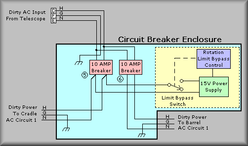
Simplified Drawing
The above drawing is a simplified version of the schematic showing the generalized
layout of the 'dirty' circuit. It shows the pin assignments of the AC power
connector, the two 10-Amp circuit breakers and the connections to the rotation
limit bypass control. Next to the circuit breakers are circled numbers that
identify them but at the panel, the circuit breakers have engraved labels to
help avoid confusions. The rotation limit bypass control receives it power from
the cradle 'dirty' circuit. This system is used to back the barrel portion of
the instrument out of a secondary limit. Obviously, these are simplified drawings
- refer to the schematics for details if troubleshooting the system.
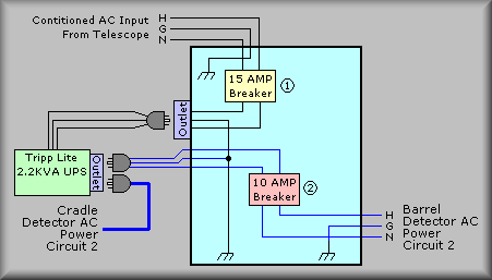
Simplified Drawing
The above block shows how the BLUE AC circuit is wired. The AC power from the
observatory feeds a 15A circuit breaker that can be used to disconnect the input
to UPS. The output of this breaker is connected to a discreet duplex outlet
box that is attached to the left-hand side of the circuit breaker box. The UPS's
AC cord is plugged into this outlet. An AC cord that is hardwired to a terminal
strip in the circuit breaker box is plugged into one of the outlets on the UPS.
This feeds the 'output' circuit breaker that takes the blue circuit through
the cable wrap and into the electronics ring on the barrel. Once in the electronics
ring, the blue circuit is wired into an electrical box that provides a covered
toggle switch to allow removing power from the circuit on the ring. Again, do
not use this switch until the CCD controllers have been shut down.
A second AC cord is plugged directly into the UPS to provide power for the cradle
Lantronix and 4-port hub.
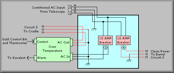
Simplified Drawing
This block shows the main AC wiring for the 'orange' circuit. Again, the 'Clean'
power from the observatory enters the circuit breaker box and this time is wired
to two circuit breakers. Circuit breaker number 3 controls the AC power to the
cradle and number 4 controls the power to the barrel. Further, the AC power
for the cradle is applied to the AC controller, labeled 'Over Temperature',
before being wired into the AC outlets. The AC controller is able to cut out
the AC to the cradle under two sets of circumstances.
First, the PC, roto, monitors the temperature in both sides of the cradle via
LM35 solid-state sensors. If the temperature of either side raises above a temperature
of 80 degrees F, the software will toggle bit 25 low which will drop the AC
control relay. Second, if for some reason roto is off line and doesn't command
the AC power off, an 85 degree thermostat is wired in parallel with the computer
control signal. At 85 degrees it will close which will also shut down the AC
power. Shown in the diagram below are the second and third AC controllers that
are mounted in Bay 4 of the electronics ring of the instrument. The controller
connected to the barrel orange circuit performs the same function as described
above except the box doesn't have the time-on relay that the is incorporated
in the cradle box (see drawings EL-3003 and EL-3102.)
Simplified Drawing
This block shows how the AC circuits are feed to the barrel. The outputs of
the orange and blue circuit breakers are wired through the cable wrap and into
bay 4. The cables are terminated into quad electrical boxes where a switch provides
a local ability to turn the circuits off. Each circuit leaves it's switch box
and is wired into it's Over-Temperature AC control box. These boxes have attached
85° F thermostats that will kill the power to the circuit if the temperature
gets too hot on the electronics ring. From these boxes the AC power is distributed
around the electronics ring.
(Back to top)
Sheet 3:
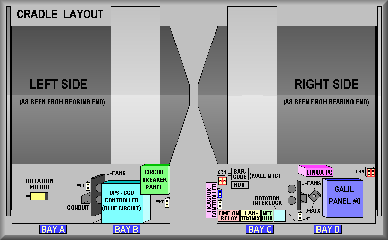
Simplified Drawing
This sheet is a pictorial reference for the location of equipment on the cradle.
Sheet 4:
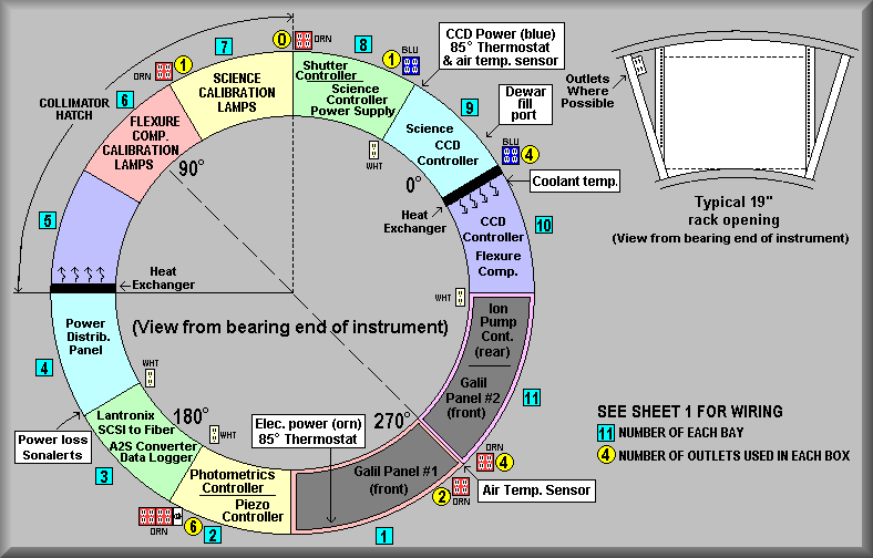
Simplified Drawing
This sheet is a pictorial reference for the location of equipment on the electronics
ring.
Sheets 5:
Sheet 5 gives notes for the various AC connectors on the instrument.
| 1.) 7-Pin Bendix connector (SP02E-22-96P {panel} and SP06E-22-96-SR{cable}).
Pinout as Follows: |
| A) - H |
(GRN) |
 |
Clean Power |
D) - H |
(RED) |
|
Dirty Power |
G) - REF. GND |
(BLK) |
| B) - N |
(ORN) |
E) - N |
(WHT) |
|
| C) - GND |
(BLU) |
F) - GND |
(WT/B) |
| 1.) 7-Pin AMP CPC connector (206137-1 {panel} and 206136-1{cable}).
Pinout as Follows: |
| 1) - H |
(GRN) |
|
Clean Power |
4) - H |
(RED) |
|
Dirty Power |
7) - REF. GND |
(BLK) |
| 2) - N |
(ORN) |
5) - N |
(WHT) |
|
| 3) - GND |
(BLU) |
6) - GND |
(WT/B) |
Sheets 6:
Sheet 6 is a pictorial layout of the terminal strips inside the circuit breaker
box. Each of the terminals are labeled with the function they provide. The light
gray blocks between two adjoining screws represent shorting strips between the
two screws.
TB-1, the top terminal strip, is wired with the two input circuits, 'clean'
and 'dirty'. The bottom of the strip connects to the input side of the circuit
breakers.
TB-2 terminals 4, and 6 receive the power from circuit breaker CB3 on
the top and send Hot, Neutral, and Ground out to the AC Over-Temperature controller.
Referring to sheet two, this wiring leaves the circuit breaker box via feedthrough
#2. The power coming back into the circuit breaker box enters via feedthrough
#3 and is wired to terminals 1, 2, and 3. The top of terminals 1, 2, and 3 are
wired to the cradle orange circuit via feedthrough #4 and to the duplex outlet
for the coolant flow meter via feedthrough #11. TB-2 terminals 7, and 9 receive
the power from circuit breaker CB5 on the top of the strip and wire to the 'dirty'
outlet on the cradle via feedthrough #10. TB-2 terminals 13, and 15 receive
the power from circuit breaker CB1 on the top and from the bottom they provide
AC power to the UPS for the blue circuit via the duplex outlet box and feedthrough
#5. UPS power returns to the box via feedthrough #6 and to the top of terminals
10 and 12. This power is then feed to breaker CB2.
TB-3 terminals 7 and 9 are wired to the output of the 'Clean' power circuit
breaker CB2. The outputs of terminals 7, 8, and 9 are wired to the barrel portion
of the instrument, where they provide the blue circuit, via feedthrough #9.
The output of circuit breaker CB6 is wired to terminals 1 and 3. the bottom
of these terminals are wired to the barrel dirty circuit upon leaving the breaker
box via feedthrough 7. The output of circuit breaker CB4 is wired to terminals
4 and 6. The bottom of these terminals are wired to the barrel clean circuit
upon leaving the breaker box via feedthrough 8. The output of circuit breaker
CB2 is wired to terminals 7 and 9. The bottom of these terminals are wired to
the barrel blue circuit upon leaving the breaker box via feedthrough 9. Terminals
10 through 17 are used for the Rotation Bypass System. The bypass system allows
an operator to move the rotator out of a secondary limit by first selecting
the Bypass position of the Normal/Bypass switch (located inside circuit breaker
panel) and then pushing the red bypass button on the back of the instrument.
This system also has a meter in line with the motor and can be used as an aide
to balancing the barrel. Terminals 10 and 11 are connected to the rotation motor.
Terminals 12 and 13 bring in the rotation stage drive power from the Galil after
it has gone through the secondary limits. At top, terminals 16 and 17 are wired
to the 15V bypass power supply. The bottom lugs are wired out of the circuit
breaker box to the Forward bypass pushbuttons via a 7-pin MS connector. Those
signal lines return to the box and are routed back out of the box to the Reverse
bypass pushbuttons via another 7-pin MS connector. They then return to the circuit
breaker box and are wired to terminals 14 and 15. For more information on the
rotation bypass system, see EL-3120
Sheets 7:
This sheet provides a pictorial representation of the circuit breaker box and
is included for reference.