Over-Temperature
Control, ![]() EL-3003
EL-3003
Schematic: deimos\TEMPMONB.sch.pdf
Page last updated: June 14, 2002
Barrel Electronics
The barrel electronics section of this manual contains descriptions of the barrel electronics for the DEIMOS Spectrograph. It corresponds to the Barrel Electronics tab in the electronics schematics binder.
Over-Temperature
Control, ![]() EL-3003
EL-3003
Schematic: deimos\TEMPMONB.sch.pdf
Page last updated: June 14, 2002
Because the electronics are enclosed in sealed compartments, any failure in the cooling system could cause the temperature in the locker to quickly rise to levels that could damage the components. This circuit is designed to prevent such a failure from destroying the electronics it that locker.
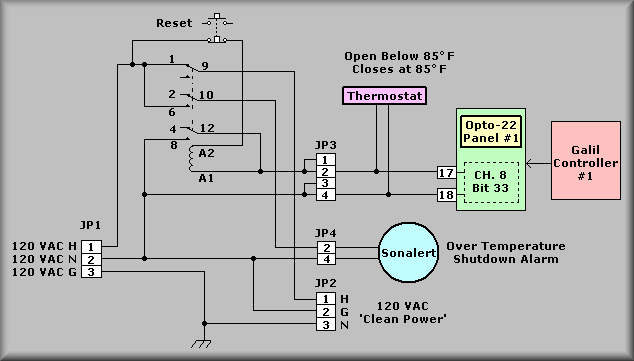
The main power for the locker is applied to terminals 1-3 of JP1 (left side of the drawing). The ground and neutral lines are sent directly to the output connector (JP2-2 & 3). The hot line is routed through one contact of the heavy duty relay to JP2 pin-1. From this connector the power is sent to the rest of the locker.
The hot line is also applied to one side of the relay's coil. If the neutral line is applied to the other side of the coil the circuit will be completed and the relay will pull in and disconnect the hot line from the output connector. The other side of the coil can be connected to the neutral line by either of two means. First, a electromechanical thermostat is mounted in the compartment. The thermostat has a trip point of 80 degrees F. If the temperature exceeds the trip point the contacts of the thermostat will close and apply the neutral to the coil of the relay. Secondly, an Opto-22 solid state relay module (channel 6 of panel 1 for controller #0 and channel 6 of panel #4 for controller #1) can also energize the coil if commanded to do so by the software. The software monitors the compartment temperature via a solid state sensor and should drop the relay well before the thermostat does.
If the relay's coil is energized it will open the contact (the top contact of the relay) that supplied power to the rest of the locker. It will also apply power to the externally mounted sonalert to alert the user that the power has been disconnected. The bottom contact in the drawing will latch the relay on so that power will be prevented from being reapplied until the manual reset button is pressed.
Mounted on the EL-3304 box is a red button labeled 'RESET'. If this button is pushed, power will be remove from the relay coil. This will restore power to the compartment. If this circuit is triggered there is a serious cooling problem. Power should not be restored until the problem is found and corrected. By design, this can not be done remotely. Thus the circuit demands that a person must open the compartment, diagnose and fix the problem,and finally press the button to reset the protection circuit.