Hamilton Spectrograph upgrade project.
Stepper Motor Driver Box, EL-4006 ![]()
The purpose of this write up is to help the technician set up the new stepper motor driver box, the DMC EL-4006, which uses the Applied Motion Products ST5-S with DMC 4080 8-channel chassis & the 4040 4-channel chassis. The internal workings of the EL-4006 include a 24VDC power supply and an interface for the limits, home & index signals from the stages to the Galil controllers. The box also has an internal cooling fan which is thermostatically controlled to turn on at 85 F. The EL-4006 stepper motor driver will live in the camera room near the Grating, Dewar Height, Dewar Focus & the Filter Wheel stages as well as in the slit room near the Slit, Decker, Cal Lamps stages, and the Guide TV Filter & Guide TV Focus stages. The Galil controllers (both the 4080 8-channel chassis & the 4040 4-channel chassis) will live in the slit room and will be interfaced to the EL-4006 stepper motor driver boxes.
Testing the Hamilton Spectrograph
Galil 4080 8-channel chassis & the 4040 4-channel
chassis with the EL-4006 Stepper Motor Drivers:
 |
 |
| FIG 1 | FIG 2 |
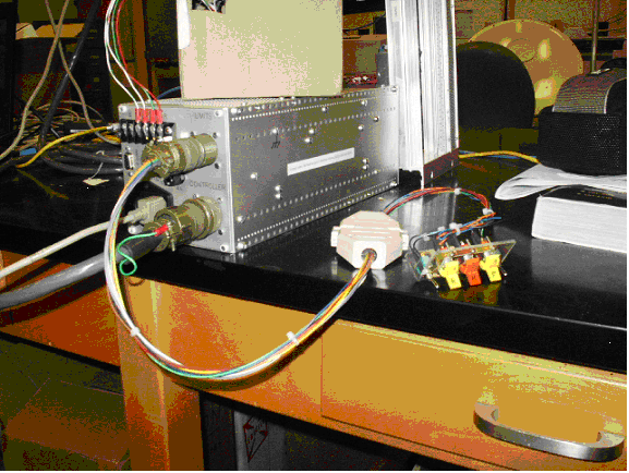
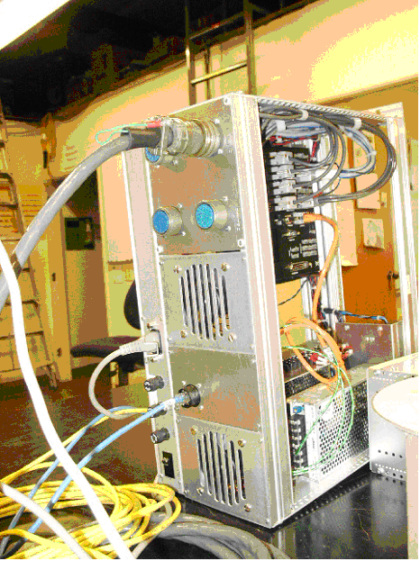
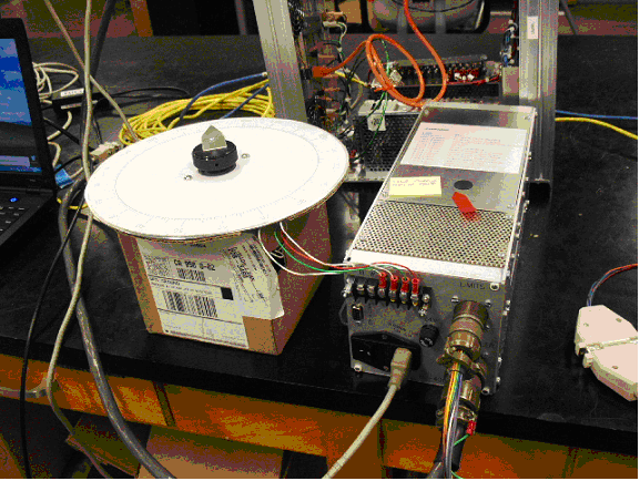
Make sure both fuses are installed, a 1.5 Amp in the AC input module and a 4 Amp in the panel mount fuse holder marked "24V" (See Fig 1). Hook up the test cable from the EL-4006 to the main controller (we will use the TV Focus Stage connector on the 4-channel chassisfor this test example, see fig 2). Hook the test limit/home switches to the EL-4006. Hook the test stepper motor with 200 count dial face indicator (See Fig 3) to the terminal strip using the Red, Green, White W/Red stripe and the White W/Green stripe wires. Plug the power cable in to the EL-4006 as well as an RS-232 cable between a PC laptop with the Applied Motion Products ST Configurator software loaded on it.
 |
| FIG 3 |
In this test we will simply use the Applied Motion Products ST Configuration to setup our EL-4006 for first time use.
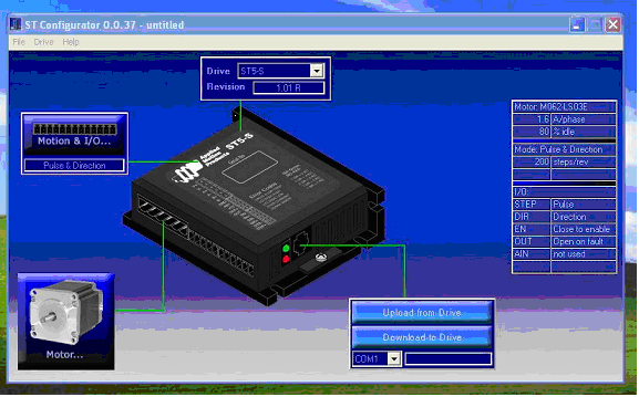
Start up the laptop and turn power on the EL-4006. Launch the ST configurator in all programs (STConfig.exe). You should see the following screen come up in Fig 4. It should be noted that you can view the Applied Motions ST5-S user manuals below. We will learn about the "Galil Tools" and test the Galil 4080 8-channel chassis & the 4040 4-channel chassis later in this document. :
| Applied Motion ST5-S user manual |
| Applied Motion ST5-S Programmer manual |
| Applied Motion ST5-S serial cable data sheet |
From the pull down Drive menu at the top select ST5-S . If it’s the first time the Applied Motion Products ST5-S has been used go to the file menu and select open. The files are located at loelhost:\My Documents\Applied Motion… for our tests I’ve saved a file called “M062-LS03E-REV2”. This will run the M062-LS03E stepper motor in our test setup.
Note that all the pictures of the ST Configurator menus are only examples and all stepper motors need to be set up to the requirements of that individual stepper motor’s data sheet. Some of the stepper motor data sheets for the Hamilton spectrograph is located at loelhost:\My Documents\HamiltonSpecUpgrade\stepper info.
 |
| FIG 4 |
Go to the “Motor” icon and click on it. Notice you can select a standard motor or custom motor. In the case of the Hamilton, we had to choose a custom motor and configure it.
 |
| FIG 5 |
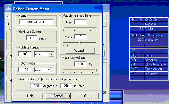
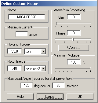
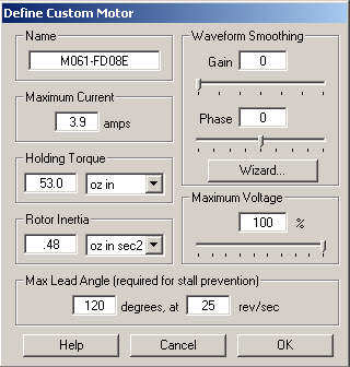
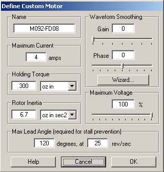
Now go to “Custom Motor” and click on Define Custom Motor.( see fig 6)
 |
| FIG 6 |
Enter the name of the motor, the max current, holding torque and rotor inertia from the data sheet. Just a note, I had a little trouble finding max lead angle so I used the default settings above.
 |
| FIG 7 |
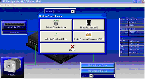
The next step is open the Motion and I/O icon to the left side of the ST Configurator. Once open you should see a window labeled Motion Control Mode (see Fig 7). Click on the Pulse and direction Icon. The window shown below in Fig 8 should now be on your screen.
 |
| FIG 8 |
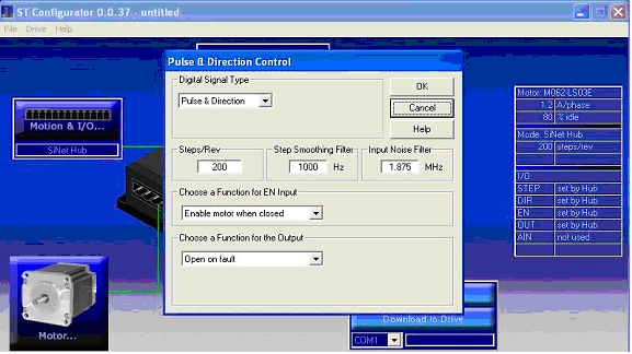
Set digital Signal Type to pulse and direction. Set the steps/Rev at 200 steps per revolution & step smoothing to 1000HZ . Make sure to set “Choose a Function for EN Input” to Enable motor when closed. The EN function is an input line directly from the Galil to enable the amplifier with a servo her (SH) command. Choose a Function for the Output and select “Open on Default” and click ok.
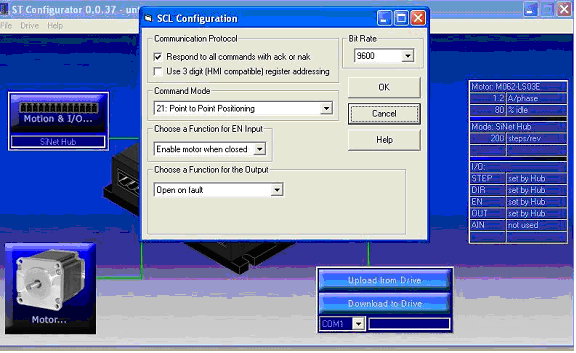
From the main menu once again click on the Motion and I/O icon to the left side of the ST Configurator. From the Motion Control Mode window (see Fig 7). Click on the Serial Command Language . The window shown below in Fig 9 should now be on your screen. Set bit Rate to 9600 and select the Enable motor when closed for the EN Input. Under Choose a function for output select Open on fault. Under communication protocol select Respond to all commands with ack or nak. Under Command Mode select 21: Point to Point Positioning
 |
| FIG 9 |
We will now set the holding current which will require Galil Ttools or equivalent console to servo and run our test setup.
In Galil Tools go to file open select project and open the file loelhost:\My Documents\Galil\Programs\Project Files from Galil Tools\HamStageA.project (see Fig 10)
If the Galil fails to communicate double check your serial RS-232 or a network connection and select Controller from the pull down menu Select Connect or choose a new connection (see Fig 11).
Once communication is established set motor speed to around
500 and servo the stepper (again these are the numbers used in our test setup)
Check limits & home
switch for functionality by using the “watch” panel on the left
of Fig 11 and observe the value change when toggling the test switches. Try
to rotate the motor 200 steps by doing a position relative in the command
line. Again observe the watch panel. The dial on the stepper motor should
make a full 360 degree rotation. Once you’re happy with the functionality
of the stepper and it’s movement corresponds to the dial, meaning that
a commanded PRA will turn the dial it’s time to adjust the holding
current.
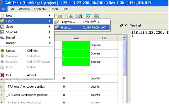 |
| FIG 10 |
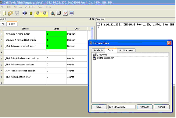 |
| FIG 11 |
Go back to the “Motor” icon in Fig 2 in the ST configurator and click on it. The window below in fig 12 should appear.
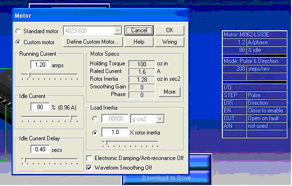 |
| FIG 12 |
Servo the stepper motor but do not command any motion. Grab the dial with your hand and see if the dial turns or if it’s held by the servo. Increase the Idle current setting if the dial can be moved. The idea here is you don’t want to have a higher idle current than needed, but you do want the system to be able to hold the stage as long as the motor is enabled. Take small steps. When any change is made you will have to download the change to stepper driver by hitting the “Download to Drive”. Retest holding current as needed and download to drive each time.
Schematic: schematics/HAM_II_drive_box_MK2_sh_2.pdf
Schematic: schematics/HAM_II_drive_box_MK2_sh_3.pdf
| Manual Parameter Entry Procedure | |
|---|---|
|
 |
 |
|---|---|
M061-FD02E
|
M061-FD08E
|
 |
 |
M062-LS03E |
M092-FD08 |