Boards
This section contains descriptions of circuit boards made for use with the Keck ADC project. It corresponds to the Boards tab in the schematics binder.
ADC LED Driver board, ![]() EL-3604
EL-3604
Schematic: schematics\ADC_LED_driver.sch.pdf
Page last updated: February 25, 2005
The LED driver board gives a visual indication of the state of the ADC instrument. Nine LEDs are arranged in the following order from top to bottom:
The network/Hardware Error LED indicates that the Galil is not putting out a pulse to indicate that it is running it's program or that it is not receiving packets over the network. The software generates a 5ms pulse every 1500 milliseconds (1.5 seconds) on output bit 33. This signal is wired to the driver board via pin 1 of J1 and then applied to pin 8 of two input NAND gate G2. The two sections of the NAND gate and the capacitor C4 and resistor R14 create a one-shot circuit with a period of 1.5 seconds that is fed to the missing-pulse circuit consisting of the transistor Q1, the NE555 timer IC, and the associated capacitors and resistors. The circuit is set for a period over 1.5 seconds and goes active (output high) if a new pulse is not received. The circuit works by charging the 1.0 uF capacitor C2 through resistor R11. If the voltage on the capacitor is allowed to reach 1/3 of Vcc then the output on pin 3 of G1 will go high indicating a loose of the pulses from the Galil controller. However, if the next pulse does arrive the Q1 will be turned on and short out the NE555's discharge pin to GND. This action causes the charging cycle to start over. The effect of the one-shot input to the missing-pulse circuit is to ensure that if the pulse train goes away and leaves the input to the board either high or low that the circuit will turn on the indicator LED on. Q2 and Q3 on the output on the circuit provide a inversion of the NE555's output and provide drive current for the LED.
The next circuit below the Net/Hardware error circuit is the BYPASS indicator. This circuit simply turns on the BYPASS LED when the Bypass +15V supply is turned on by entering bypass mode. Note: Once in bypass mode, the operator must manually depress the RESET button on the front panel of the electronics cabinet to resume operation.
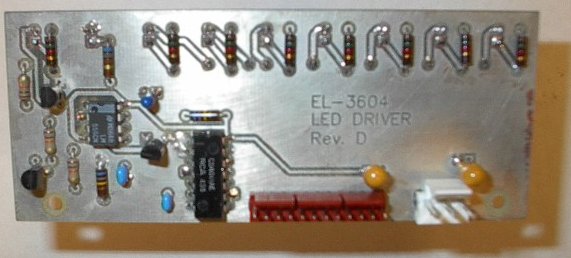
LED Driver front view
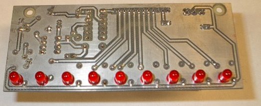
LED Driver rear view