Barrel Signal Assignments
The barrel signal assignment section of this manual contains
descriptions of the signal assignments for the DEIMOS Spectrograph. It corresponds
to the Barrel Signal Assignment tab in the electronics schematics binder.
Schematics: schematics\SIGNALS1.sch.pdf, schematics\SIGNALS2.sch.pdf, schematics\SIGNALS3.sch.pdf,
schematics\SIGNALS4.sch.pdf
Page last updated: June 14, 2002
These four sheets, and drawings EL-3026, EL-3027, EL-3028, and
EL-3029, show the signal assignments for the
Galil DMC-1580-72
controllers and amplifiers that live in the electronics ring. We will look at
several of the sheets to illustrate how to use the two different types of sheets.
Sheets 3020 through 3023 describe the signal assignments at the Galil controller
connectors. Sheets 3026 through 3029 describe the signal assignments at the
terminal board of the Galil AMP-1140 panel. Further, schematic
EL-1266
in the
Miscellaneous Schematics section of this manual provides
the signal assignments for each connector mounted on the various amplifier/connector
assemblies. Galil controllers #1 and #2 are each capable of running eight axes.
A third Galil controller lives in the cradle portion of the instrument and is
covered in the
Cradle Signal Assignment
section of this manual.
Controller
1, Amplifier A, Stages A through D 
First, sheet EL-3020 contains three boxes. On the left side of the sheet,
the box gives the signals for J2 labeled 'Main'. This denotes the ribbon cable
connector on the top of the controller. This cable connects into a mating connector
on the AMP-1140 module. The signals that we use are the controller's limit switch
inputs for the TV Filter and the TV Focus stage on pins 6 through 11. In the
case of the filter wheel stage, the forward and reverse limits are not wired
because the stage is an unconstrained rotary stages, and is able to rotate continuously.
Pins 25 through 28 are the analog control voltage and enable signals for these
stages. The controller generates a +/- 10V control signal that is supplied to
the servo amplifier. Note, the controller is also capable of generating stepper
motor output but we only use servo motors in this equipment. The last set of
signals that we connect to are the encoder inputs on pins 33 through 44. The
drawing shows the stage's motor encoder connections. As is shown on the diagram,
the X and Y axes are used on this controller but the Z and W axes are spares
that are available for future expansion. Also note, that Galil allows the axes
to be known as either X, Y, Z, and W, or as A, B, C, and D. When using a controller
with more then four axes, the second four are E, F, G, and H. Because we are
using the eight axes model, we designate our stages as A through H. A bit of
confusion can arise when examining the labels on the Galil amplifier board because
they use X, Y, Z, and W on all of their amplifiers. Thus, the labels on the
second amplifier have to be mapped into E, F, G, and H. Schematics EL-3026 through
EL-3029 provide that mapping for the DEIMOS instrument electronics.
The second box on the sheet shows the J5 general I/O signal
connections. We are using the first three analog inputs, pins 1-3, in conjunction
with digital outputs 5, 6, and 7 to read the analog signals from the
EL-1230
24-channel analog input board. This board provides inputs for monitoring the
various power supply voltages and low resolution temperature sensors. Next,
digital outputs 1 through 4 are used to turn on the optical slotted switch fiducials
for each of the stages (refer to the drawing below to see how the switches are
wired.) These are Optek OPB970T55 slotted optical switches. The last set of
signals we use in this block are digital input bits 1 through 4. These are wired
to the secondary limit switches again, as seen on the schematic below. Note
that to conserve I/O bits, we have wired the
Normally
Closed contacts
of both the forward and reverse secondary limits in series. Note too, that this
gives us an error condition if any of the stage's connectors are disconnected
for any reason. The second pole of these limits are used to interrupt the power
to the stage servo motor. This means that if a stage moves beyond it's software
limit and then moves beyond it's primary hardware limit and into it's secondary
limit, the
only way to move it back out is to manually move the
stage by turning it's motor shaft!
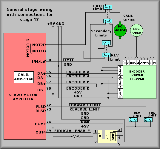
Example Stage connections
The last box shows the J3 auxiliary encoder connections. On
DEIMOS, we use encoders in two different modes. Most stages use the servo motor
encoder to close the servo loop and to position the stage. We refer to this
as
single loop or
normal encoding and there won't be any entries
in the third box for a stage with this configuration. On the three grating tilt
stages and the instrument rotation stage however, we use
dual loop encoding.
In this scheme, the motor encoder is used to close the servo loop but positioning
is done with the secondary encoder. For stages using this configuration there
will be entries in the third box. In the case of the DEIMOS grating tilt mechanisms,
a Gurley Precision Instruments encoder is used as the second encoder. The model
835 encoders that we use have a total resolution of 900,000 counts per revolution(11,250
lines times 4 for quadrature and times 20 for interpolation amplifier. (See
discussion on
two-loop encoding for more details.)
The note under the first box points out that though the stages
are marked as X, Y, Z, and W, but we are referring to them as A, B, C, and D.
Either designation is allowed by the Galil controller but because we are using
eight axes, we have opted to use A through H.
Controller
1, Amplifier B, Stages E through H
The second sheet,
EL-3021, shows the
connections for the CCD Focus stage, The CCD Translation stage, and Filter Wheel
stage. On this controller, the fourth axis, H, is left for future expansion.
None of the stages connected to this amplifier have auxiliary encoders attached
to them. Because the second amplifier does not have analog inputs available,
there isn't a 24-channel analog input board connected to this amplifier panel.
Controller
2, Amplifier A, Stages A through D
The third sheet,
EL-3022 shows the
three Grating Tilt stages and the grating slider stage. The leftmost and center
boxes describe the connections to the controller. The stages are wired in the
same manner as the other stages. However, a difference exists in that the index
signal from each of the grating tilt stages is connected to the index input
for these stages. This detail shows up on the EL-3028 drawing but not here because
these are general useThe third box at the right hand side of the sheet shows
the connections for the three dual-loop encoded Grating tilt stages. The EL-1272
stage interconnect box that is used for the tilt stages contains the necessary
wires to bring the Gurley encoder index signal into the main encoder index input.
The Grating Slider stage does not include an auxiliary encoder.
This points out the flexibility of the Galil system. In the
case of the Grating Tilt stages we are using
two-loop encoding. By connecting the Renishaw
encoder to the auxiliary encoder input we are able to position to within +/-
1.44 arc seconds of the specified position. The Grating Slide stage does not
need this sensitivity and thus the motor encoder is the only encoder used.
Controller
2, Amplifier B, Stages E through H
The last sheet,
EL-3023 shows the
connection for the Slitmask stage. These connections are only part of the overall
workings of the stage. It represents the 'scissors jack' portion of the stage.
The stage also includes a pneumatic cylinder that pushes the slit mask into
the beam. Signals for the pneumatic stage are described under
EL-3037
and
EL-3038.