As seen on EL-3001 sheet 1, each panel is capable of running up to eight separate servo motor stages. Each controller panel has unused stages that provide for some future expansion.
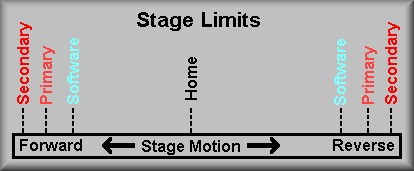
Each of the ten stages operate in one of two modes depending on the stage's function. The first type, a rotary stage, is capable of continuos movement in either direction. This type of stage is positioned relative to a home position. This position is determined in each case by using an optical slotted switch which provides the function of a fiducial. Once the stage has been 'homed' the targeted position is achieved by counting the encoder pulses. The second type of stage is a constrained motion stage. This type of stage is constrained by forward and reverse limits. Each stage has three separate limits for both forward and reverse motion. The first limit that the stage encounters is the software limit. The routines moving the stage have a maximum travel limit at which the software stops further motion the that direction. In case something goes wrong, the stage next encounters the primary hardware limit switch. This switch is connected to the motor controller and signals it to turn off the motor. The final hardware limit switch, the secondary limit, is wired in series with the motor power lead and shuts off power to the motor when encountered. It also is connected to a digital input bit on the Galil motor controller. This lets the upper levels of software know the stage has traveled into the final limit.
In normal operation, the stage should never make it to any of the three limits. If something goes wrong each limit should cause the stage motion to stop. If a moving stage makes it to either the software limit or the primary limit the stage can be moved only in the opposite direction to back out of the limit. In the case of the secondary limit however, the motor power is held off by the limit and the only way to back out of this limit is to manually turn the shaft of the motor!
The servo motor stages are designated by a controller number and a stage letter. The cradle controller is designated #0 and the barrel controllers are designated #1 and #2 (for the convenience of the programmers.) Each of the controllers drive up to 8 stages designated A through H. Be careful of the Galil labeling on the AMP-1100 panels. Galil provides them with generic labels of X,Y,Z &W. This can be confusing especially when looking at the second AMP-1140. Though it is labeled as X-W, as programmed and referred to in our documentation they are E,F,G & H. Also, the labeling of the various I/O bits provided on the second AMP are not correct. To get the correct names of these signals look either in the appendix of the DMC-1500 manual or at EL-3020, EL-3021, EL-3022 and EL-3023.
There are variations among the stages in the type and number of encoder(s) used. See item 4 below for a discussion.
(Note: click here for Opto-22 website)Throughout this project we have used Opto-22 Generation 4 I/O modules to isolate the input and output signal to the Galil controller. Galil designed their 72-bit I/O expansion board to work with Opto-22's G4PB24 24-channel I/O mounting rack. This allows for easy interconnection via a 50 conductor ribbon cable. Three such boards can connect to the Galil with three cables. Galil's scheme in assigning I/O bits is to allow the first 24 bits to be programmed for either input or output, the last group of 48 is always inputs. In our implementation, the first group of 24 bits are always outputs and the last 48 bits are inputs.We have populated the I/O module racks with four different types of modules. For outputs we use either an AC module, G4OAC5, for such jobs as turning on and off AC fans, lamps, and the like or a G4ODC5R for controlling +5V logic devices such as LEDs. For input signals we use G4IAC5 to sense the AC voltage signal from the Ion Pump Controller and G4IDC5D modules for logic level signals. These I/O boards are shown pictorially on the following schematics: EL-3034, EL-3035, EL-3036, EL-3037, EL-3038, EL-3039, for the barrel, and EL-3113 and EL-3115 for the cradle.
In our spares we include one each of the G4OAC5MA and G4IDC5MA manual On/Off automatic Diagnostic relays for help in troubleshooting.
To obtain the required resolution, we have implemented four types of encoder feedback for the servo motor stages. Schematics EL-1236 and EL-1236R for single loop, and EL-1272NORM and EL-1272REV for dual loop encoding.
1. The first type, single-loop encoding, is the normal way of running a servo motor. The motor encoder is connected directly to the controller and we position to the motor encoder reading. single-loop encoding is used on the Guide TV Focus, Guide TV Filter Wheel, CCD Focus, CCD Translation, Grating Slide, and Slitmask stages.
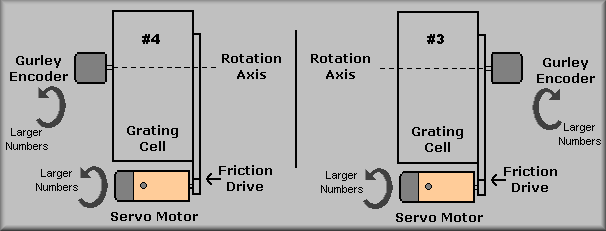
2. The other type of encoding that we use is dual-loop encoding. In this scheme, the load encoder is wired (via the EL-1272 interconnect box) into the motor encoder's input and the motor encoder is wired into the auxiliary input. This allows the stage to servo on the load encoder giving finer control of the positioning of the stage. In DEIMOS, we are using Gurley Precision 835 series encoders on the grating tilt stages. These are mounted on axis on the tilt stages and because of physical restraints, the encoders are mounted to different sides on the different tilt stages. Thus, the stage interconnect box on tilt #4 is wired 'normally' but tilt #3 is wired in 'reverse'. To accommadate the opposite rotation of the encoder relative to the servo motor encoder, the 'A' and 'B' phases of the encoder are exchanged at the terminal strip inside the stage interconnect boxes (EL-1272REV.)
Renishaw encoders as the main encoders in the three collimator stages, Filter Wheel, Slitmask Wheel, and Aperture Wheel stages. The Collimator stages use model RGH22Y .1 micron encoders while the other stages use the model RGH22D 5 micron encoder. The Renishaw units are linear encoders that read a tape strip. In our application the tape is applied to the moving portion of the collimator actuators and to the edge of the moving wheel of the three wheel stages. The read heads are then aligned for optimum performance. The heads have a two colored LED that is used for alignment. When the LED is green the encoder has locked onto the tape. If the indicator turns red the readings are no longer guaranteed. This doesn't necessarily mean the the encoder has lost it's position but it may have and it should be adjusted.