Cradle Wiring
The cradle stage wiring section of this manual contains descriptions
of the rotation stage wiring and associated systems for the cradle portion of
the DEIMOS Spectrograph. It corresponds to the Cradle Stage Wiring tab in the
electronics schematics binder.
Rotation Stage,  EL-3120
Schematic: deimos\ROTATION.sch.pdf
Page last updated: February 18, 2003
The DEIMOS instrument rotation stage is run by a Linux PC with
a Galil DMC-1920 Servo Motor Driver card installed. The PC talks to the instrument
control computer over the private network. It also has a second network card
that attaches it to the public network for diagnostic purposes. The rotation
stage allows just over two full rotations, 790 degrees, of the barrel portion
of the instrument. To make the two revolutions possible a chain and sprockets
were added to the back of the instrument that run a puck/limit actuator back
and forth from one side of the cradle to the other. The sprockets were sized
to make the two revolutions of the barrel move the puck between the stage limit
switches. An over-center limit switch was added at the middle of the travel
of the puck to tell the PC which revolution the barrel is currently in. The
limit switches used for end of travel of the stage consist of one over-center
primary limit and one standard DPDT secondary limit switch. The over-center
type primary limits allows the puck to toggle them and then continue on to actuate
the secondary limits. Like other stages, the secondary limit switches cut power
to the motor but, unlike other stages, there is a system to move the stage back
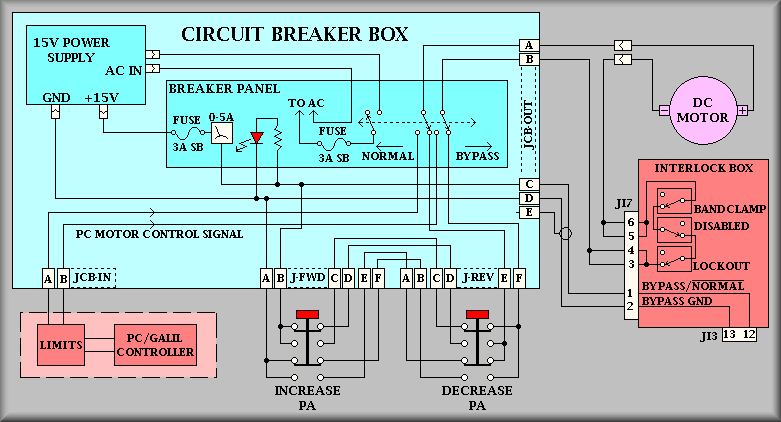
out of a rotation limit. To do so, the operator must open the circuit breaker
panel on the instrument and flip the Normal/Bypass switch to the bypass
position. With this done, the instrument can be backed out of the limit by first,
locating the puck to determine which limit is tripped, then push and hold the
red button above that limit. This will rotate the instrument at a safe speed
in the correction to disengage from the limit. As a side note, these buttons
can also be used to check the balance of the instrument. To do so, one person
should watch the current meter next to the Normal/Bypass switch while another
person actuates the pushbuttons one at a time. When the instrument is in balance,
the current draw should be about the same in both directions of rotation. After
using the bypass system be sure to set the switch back to Normal.
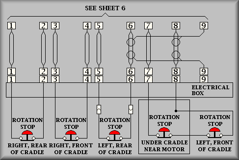
For safety reasons, there are a number of other limit switches on the instrument
that interact with the rotation. First, there are the 'Rotation Stop' buttons
near each corner of the instrument and next to the drive motor. These are intended
to act like a panic switch that anyone can push to stop the instrument rotation
in an emergency. Once one of these buttons are pushed, the instrument will not
be able to start rotating until the green 'Reset' button in C-Bay is depressed.
To restore rotation, an operator must remove the cover to C-Bay and push the
green 'Reset' pushbutton. Besides the 'Rotation Stop' limits, there are also
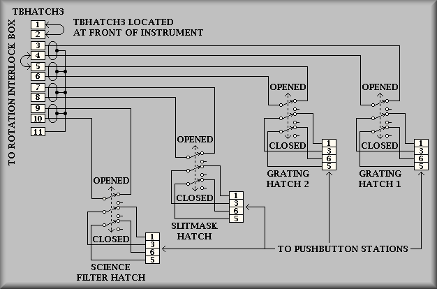
the hatch limit switches. These are mounted at each of the opening hatches on
the barrel of the instrument. They are: Dewar 1 Hatch, Dewar 2 Hatch, and the
Man Hatch that allow entrance into the barrel, and the filter wheel, slitmask,
and grating hatches that allow access to the changeable elements of the spectrograph.
If any one or more of these hatches are open, an interlocking relay will stop
or prevent rotation. Unlike the 'Rotation Stop' switches, however, rotation
will be restored once the hatch is re-closed. The last limit switch in the current
path of the rotation motor is the 'Band Clamp' limit switch. This switch is
actuated by the band clamp which physically locks the drive disk of the barrel
to the cradle. The limit switch keeps power from being applied when locked.
Because of the complexity of the rotation stage, a manual paddle has been provided
to assist in operation and troubleshooting. The paddle has the ability to operate
the stage and provide feedback to the operator as to the status of the stage.
The paddle is used by first, selecting 'Manual' on the toggle switch and then
selecting the desired function via the two paddlewheel switched and finally
pushing the 'FWD' or 'REV' button to start movement. Also, when in 'Manual'
mode various LED's are used to show the status of the stage. Above the 'FWD'
and the 'REV' pushbuttons are red LED's that are illuminated when the stage
is in the limit for that direction. If both of these LED's are blinking, that
means that the stage has not been initialized. Between the 'FWD' and the 'REV'
pushbuttons is a yellow LED that is lit when the stage is moving. There is also
a line of LED's on the left side of the paddle. As marked, these LED's are lit
when a limit condition occurs. The possible limits are, from top to bottom:
'Band Brake On', 'Panic Button Pushed' (Rotation Stop), 'ESTOP Active' (Observatory
ESTOP), 'Rotation Bypassed', and 'Hatch Opened'. Again, any one of these limits
will stop the instrument from rotating.
Various modes of rotation are available to the operator. The mode switch will
let you move at a fast (switch setting 0) or slow (switch setting 1) jog speed
where that barrel will rotate while the direction pushbutton is depressed. If
the 'Position Switch' mode (switch setting 2) is selected the instrument will
move to the discrete position selected by the 'Position' paddlewheel switch.
With 'Next 90°' selected (switch setting 3) the instrument will rotate to
the next 90° position when either the 'FWD' or 'REV' button is pushed. The
direction of rotation will depend on which direction button is pushed. In the
'Sound' mode (switch setting 4), ????????? The
'Home' (switch setting 7) will, when selected and a direction button is pushed,
start the homing sequence for the rotation stage. When homing, the direction
button that button that is pushed is irrelevant, the computer will determine
and use the correct rotation direction to home properly. For 'Mode' switch position
3, 'Posn. Sw.', the positioning modes are as follows:
| Switch setting |
Label |
Function |
| 0 |
-90° |
Move directly to -90° for ?????? |
| 1 |
Dewar Fill R |
Move dewar fill tube for access from the right side
of the instrument |
| 2 |
Dewar Fill L |
Move dewar fill tube for access from the left side of
the instrument |
| 3 |
Grating Access |
Rotate to where grating change hatch is positioned for
changing gratings |
| 4 |
Slitmask Access |
Rotate to where slitmask change hatch is positioned
for changing slitmasks |
| 5 |
Filter Access |
Rotate to where filter change hatch is positioned for
changing filters |
| 6 |
Neg. Limit |
Move to negative primary limit |
| 7 |
Pos. Limit |
Move to positive primary limit |
Sheet 1:
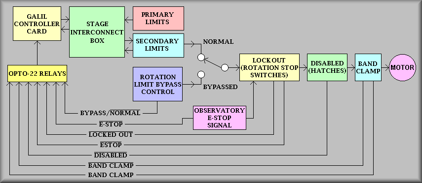
Simplified drawing
Sheet 1 gives a block diagram of the the instrument rotation
stage. At the left side of the drawing is the Galil controller and at the
right side is the Galil 500/1000 servo motor. The intervening boxes show the
various limit switches that combine to assure safe operation of the instrument
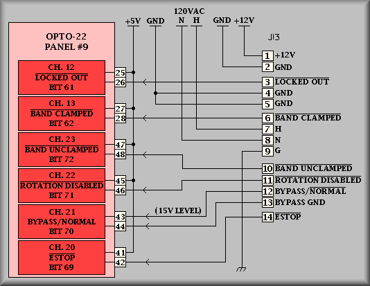
rotation. Attached beneath the Galil controller block is the Opto-22 relay
rack. With the exception of the primary and secondary limits, all conditions
that can disallow rotation are monitored here. Shown as black lines at the
bottom are the various signals that the Galil controller, and thus the PC,
monitor to determine that it is safe to rotate the instrument.
The first three blocks from the left show the standard scheme for running
a stage. However, because of the complexity of the motion and the sheer size
of the rotating portion of the instrument, other safeties have been added
to the
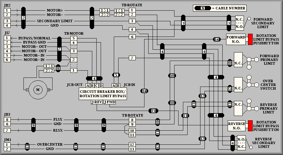
Summery-- For
the motor to run, the signal path must be complete. Each block to the right
of the 'Stage Interconnect Box' represent physical switches that must be 'made'
in order for the circuit to be completed. The Normal/Bypassed switch
allows operation from either the computer or the Bypass Control system. Note
that the Bypass system only bypasses the Primary and Secondary limits - all
other limits must be correct before the Bypass Control system will rotate
the instrument.
Sheet 2:
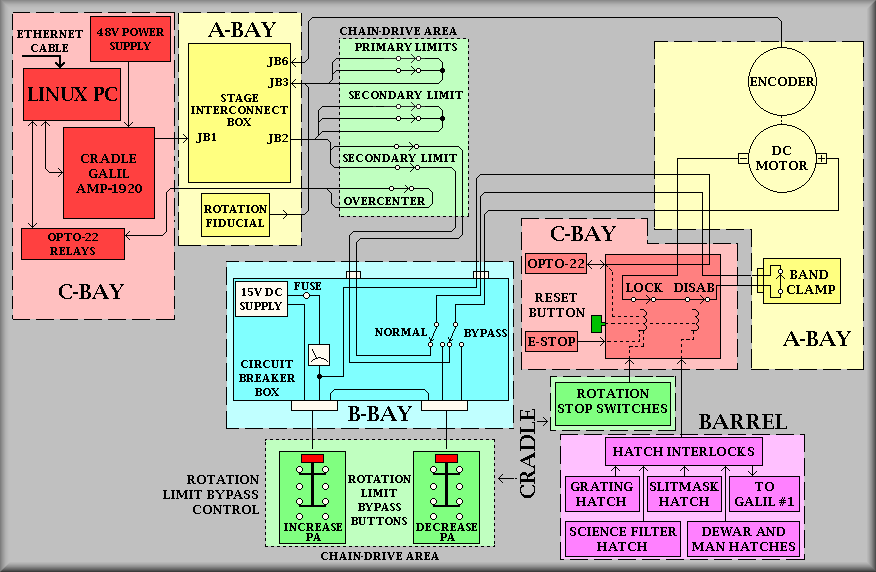
Simplified drawing
As the page title says, this is a more detailed block diagram
for the rotation stage. At this level, most of the cables and some of the
connectors and terminal strips are called out. Also, notice that each block
has a 'Bay' reference. These correspond to the bay markings on the instrument.
On the left side, the first first block details the Linux PC. The PC talks
to the instrument control computer (keamano) via the private net. The PC has
a Galil DMC-1820 motor control card installed which connects via a 100-pin
to the AMP-1920 servo motor amplifier. Also, a block representing the 48V
Lambda power supply is shown connecting to the amplifier via four wires.
Sheet 3:
Simplified drawing
Sheet 4:
Simplified drawing
Sheet 5:
Simplified drawing
Sheet 6:
 Simplified
drawing
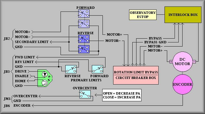
Simplified
drawing
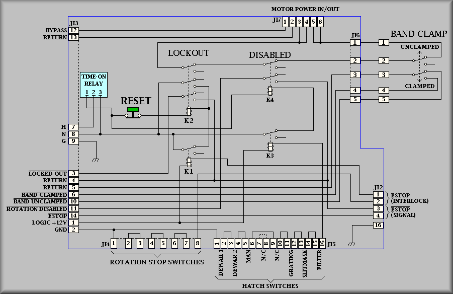
Above is a representation of the Rotation Interlock Box. Also
shown is the rotation Band Clamp. The Band Clamp is a long metal strap that
is used to clamp the rotating barrel of the instrument to the cradle. When
applied, the clamping pressure is great enough to keep the barrel moving even
with the instrument being out of balance. In fact, we have had people climbing
on the barrel
Sheet 7:
Simplified drawing
Sheet 8:
Simplified drawing
Simplified drawing
Sheet 9:
Simplified drawing
Sheet 10:
Simplified drawing
Sheet 11:
Simplified drawing
Sheet 12:
Simplified drawing