Barrel Stage Wiring
The barrel stage wiring section of this manual contains descriptions of the individual stage wiring for the barrel portion of the DEIMOS Spectrograph. It corresponds to the Barrel Stage Wiring tab in the electronics schematics binder.
Grating Push Button Station,
![]() EL-3071
EL-3071
Schematic: schematics/GRATEPB.sch.pdf
Page last updated: January 24, 2003
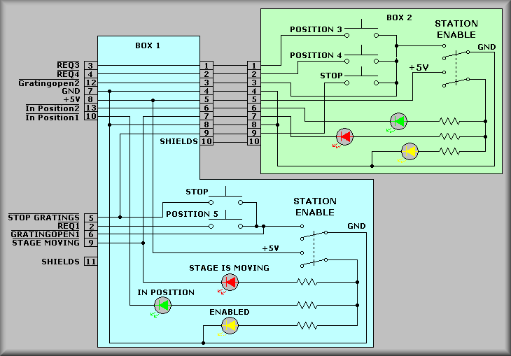
Simplified Drawing
The Grating Pushbutton Station is used to manually move the
grating stage into the grating load position. The station consists of two
separate boxes with controls to move the stage or stop the stage movement.
At this time, only box 2 is active due to the fact that the third grating
(labeled 'Position 5' above) has not been implemented. At
the right hand side of the green box is the Station Enable
switch. This switch is a DPDT limit switch that is actuated by opening the
grating access door. Once actuated, +5V is applied to and turns on the yellow
ENABLED LED. At the same time, the controller software will
signal the control computer that the stage is under manual control. The red
STAGE IS MOVING and green IN POSITION can
then be turned on by the controller software to indicate the status of the
stage. If no button has been pushed, the green LED should be on indicating
that the stage is in an ordinal position. At this point the software polls
the POSITION 3 and POSITION 4 pushbuttons
via signals *REQ3 and *REQ4. If one of the pushbuttons is pushed the controller
moves the desired grating into it's unload position. Note: during these manual
moves all limits are still in effect. If the operator detects a problem
while the stage is moving they can press the STOP button to signal the controller
to terminate the movement. The operator should be aware that this is a software
controlled move and if the controller or some link in the signal chain fails
that the proper response is to allow the stage to move into it's secondary
limit. The hope is to maintain the safety of the operator - when the stage
hits the secondary limit the power will be removed from the stage motor.
Under software control the red STAGE IS MOVING LED will be
turned on until the stage comes to a complete stop and the green IN
POSITION LED will turn on. Once the grating has been changed, closing
the access door will notify the controller software that the stage control
is ready to be released back to the control computer
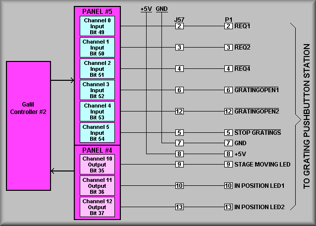
Simplified Drawing
Sheet 2 shows the wiring, connector, and bit assignments for
the pushbutton station.