Barrel Electronics
The barrel electronics section of this manual contains descriptions
of the barrel electronics for the DEIMOS Spectrograph. It corresponds to the
Barrel Electronics tab in the electronics schematics binder.
Calibration
Lamp Wiring,  EL-3011
Schematic: schematics/LAMPS.sch.pdf
Page last updated: June 20, 2002
Photos: Lamp Power Supplies 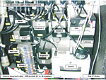
Photos: 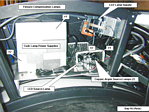
The calibration lamp system consists of I/O bits, AC wiring, power supplies,
and lamps. In the case of the copper lamps and Flexure Compensation
System LED there is also fiber optic cables that carry the light
to the front of the instrument while the lamps remain in the electronics enclosure.
The I/O bits turn the AC power off and on to the power supply of each bulb via
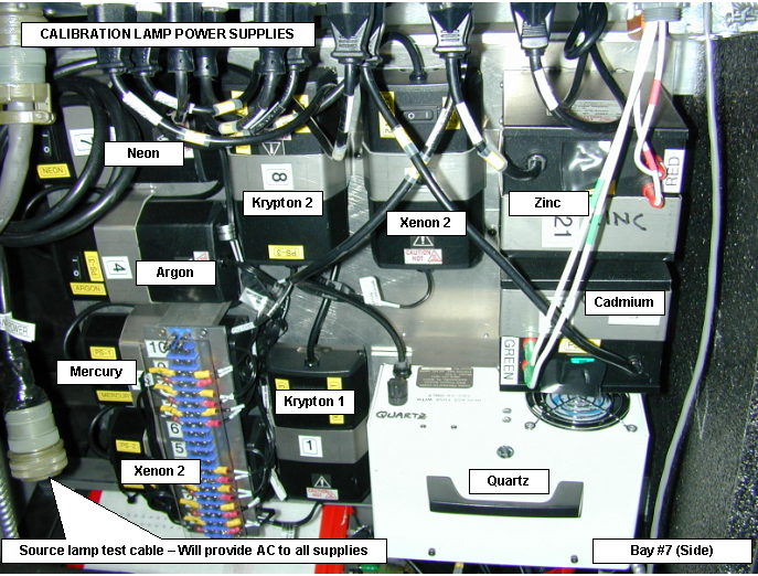
the Opto-22 relay modules. The power supplies for the rest of the calibration
lamps are mounted on a plate in bay 7 of the electronics ring. The individual
power switches are left in the 'ON' position so that they can be controlled
via their power cords. For safety reasons the entrance hatch is interlocked
to the AC power source for the krypton, xenon, mercury, argon, neon, cadmium,
and zinc lamps. These lamps are located near the entrance hatch and power is
removed from them when the hatch is open. The quartz, copper, and FCS LED are
not interlocked because these lamps are located in the electronics ring.
The full schematic
shows the wiring details.
Calibration lamps simplified drawing 1.
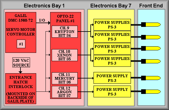
Sheet 1:
(Refer to EL-3011 schematic, sheet
1) On the left-hand side of the schematic is a block representing the Galil
controller. The block next to it represents the expansion I/O and the Opto-22
relay modules. The calibration lamps are controlled via the Opto-22 relays.
As can be seen on the above simplified schematics, each of the Pen-Ray calibration
lamps are interlocked with the front hatch. On the normal schematic the interlock
mechanism isn't as clear but terminal 1 of terminal strip TBE has been isolated
from the unswitched terminals and is wired through the lamp interlock box (wiring
details ore on sheet 3.) J52 is a 24-pin CPC connector that is mounted on the
Galil controller panel #1. A large cable is then routed to Bay 7 of the electronics
ring where it connects to a bank of ganged double duplex outlet boxes via a
24-pin MS connector labeled J40. The outlet boxes are shown in the center of
the drawing. This scheme allows us to use the original power cords of the calibrations
lamp power supplies and facilitate replacement of one if needed. Note, however,
that the power cords, for the original installation, were shortened to lower
the level of cable congestion on the power supply mounting panel. The topmost
duplex outlet is shown to have both outlets ganged together. This signifies
that the two Krypton are turned on at the same time by asserting (clearing)
bit 34. Due to the faintness of this lamp, two are always used at the same time.
As shown below the Krypton lamps, the Xenon lamps are turned on in the same
fashion via bit 35. The Mercury lamp is turned on by bit 36 and is wired to
one of the two outlets on the next duplex plate. The last lamp on this page
is the Argon lamp on bit 37 and wired to the bottom outlet on the third duplex
plate. In each case on this page, the power supply used is a UV Products model
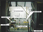
PS-3. The diagram shows the outputs of these power supplies connecting to either
TB1-A or TB1-B. These designations refer to two terminal strips at the front
of the instrument. Looking from the telescope into the instrument, TB1-A is
on the right side and TB1-B is on the left side of the calibration lamp mounting
plate when the instrument is rotated to 270 degrees. The lamps themselves connect
to an in-line connector that is in turn wired to the output side of TB1-A or
TB1-B.
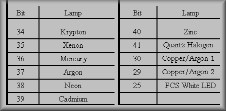
Calibration lamp I/O bits.
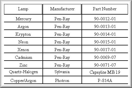
Calibration lamp part numbers
Calibration lamps simplified drawing 2.
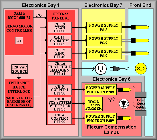
Sheet 2:
(Refer to
EL-3011
schematic, sheet 2) On the left-hand side of the schematic is a red block representing
the Galil controller. The red block to the right of it represents the expansion
I/O and the Opto-22 relay modules. The calibration lamps are controlled via
these Opto-22 relays. The red block below the Galil controller represents the
lamp/hatch interlock for the Pen-Ray Neon, Cadmium, and Zinc calibration lamps.
On the normal schematic the interlock is shown above the Opto-22 relays. Terminal
1 of terminal strip TBE has been isolated from the unswitched terminals and
is wired through the lamp interlock box (wiring details are on sheet 3.) J52
is a 24-pin CPC connector that is mounted on Galil controller panel #1. A large
cable is then routed to Bay 7 of the electronics ring where it connects to a
bank of ganged double duplex outlet boxes via a 24-pin MS connector labeled
J40. The outlet boxes are shown in the center of the drawing. This scheme allows
us to use the original power cords of the calibrations lamp power supplies and
facilitate replacement of one if needed. Note, however, that the power cords
for the original installation were shortened to lower the level of cable congestion
on the power supply mounting panel. The topmost duplex outlet is wired for both
the Neon and Cadmium lamps. The Neon lamp is controlled by I/O bit 38 and connects
via outlet 5. The Cadmium is controlled by bit 39 and connects via outlet 6.
The Zinc lamp is controlled by bit 40 and connects via outlet 7. Note on the
diagram that the Cadmium and Zinc lamps are wired in using banana plugs. These
lamps run on 6kV so the wire used is high voltage Teflon wire terminated in
the banana plugs. This makes the connections unique and capable of passing the
high voltage.
The rest of the lamps are not wired through the interlock because either they
are not harmful (Halogen lamp and the white LED) or are not mounted at the front
of the instrument (Copper lamps.) The Quartz Halogen is a common 120V AC lamp
purchased at a hardware store. It is controlled by I/O bit 41 and is wired to
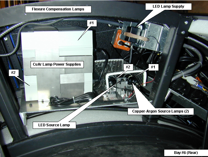
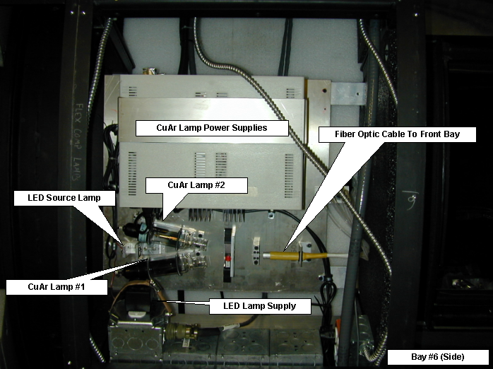
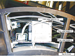
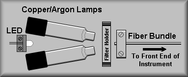
a duplex outlet at the front of the instrument. As shown below, the white LED
is used for the Flexure Compensation System and is mounted on the copper lamp
plate. It sits behind and centered between the two Copper/Argon lamps in bay
#6. There is a pot inline with the LED which allows for altering the brightness.
The wall transformer is plugged into a duplex outlet just above and behind the
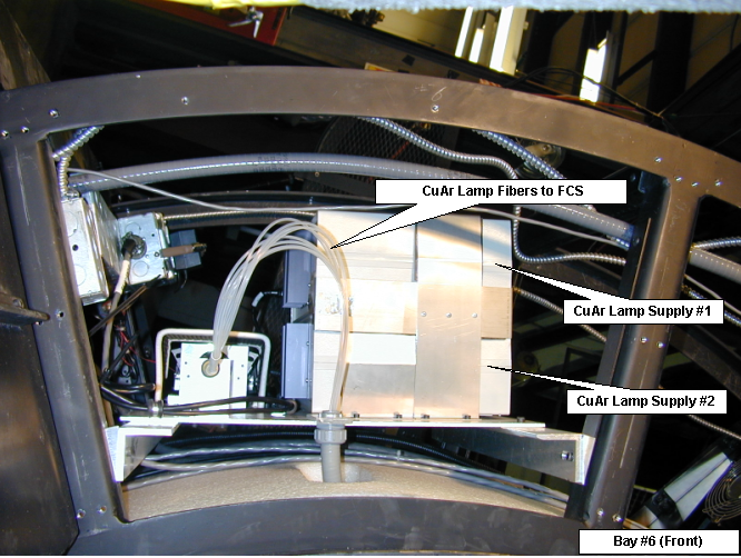
copper lamp plate. The Copper/Argon lamps are mounted on a plate in electronics
bay 6. They can be individually controlled via bits 29 and 30. They are angled
so that they both illuminate the fiber bundle that directs the light onto the
FCS CCDs in the dewar.
Sheet 3:
This sheet shows the wiring of the Entrance Hatch/Lamp Interlock
Box. The purpose of this box is to make sure that the calibration lamps cannot
be on when the entrance hatch is open. It is thought that if the hatch is opened
other then when the instrument is in use someone could look in at the lamps
and possibly cause eye damage. To avoid this, a magnetic limit switch was added
to the second hatch Bimba cylinder to control a relay that in turn disconnects
the AC power to the front end mounted calibration lamps. The exception to the
rule is the Quartz/Halogen lamp. Because it does not contain light at harmful
wavelengths it's power is not interrupted.
At the top of the drawing is the AC input into the box. A 5 ampere fuse is used
to protect the lamp system. The AC is fed to contacts 5 and 6 of the large contactor
relay K1. This relay is activated when the the signal circuit relay K2 is activated.
When activated, the AC power is applied to contacts 9 and 10 and then leaves
the box to power terminals 1 and 12 of the main AC power terminal strip TBE.
From there, the AC is routed to the Opto-22 relays that power the calibration
lamps. K1 contacts 4 and 12 are wired to the LAMPS LOCKED OUT input of
Opto-22 panel #2 channel 8, input bit 57 (see sheet 4.) This signal informs
the control computer of the state of the lockout.
The lower relay, K2, is activated by the Entrence Hatch Bimba limit switch.
While the hatch is closed, 12 volts are applied to the coil and the contacts
that complete the coil circuit for K1 are closed. When the hatch is opened,
the coil circuit of relay K2 is broken which in turn opens relay K1. The 1N4004
diode is in the circuit to provide 'kick back' voltages from harming the 12V
supply. In the middle of the sheet is the Lamp Interlock Junction box. It supplies
a convienent break out of the three possible connection sets. The right side
of the drawing shows the current wiring state of the limit switches at the front
of the instrument. Though not implemented, connections are available for another
access hatch limit switch (bottom) and an limit switch override input (top.)
The upper right hand corner of the drawing calls out the various connector used
in the system.
Sheet 4:
This drawing gives the details of how the LAMPS LOCKED OUT
signal is wired back to Opto-22 panel #2. J46 provides a ground on pin 2. The
contacts on relay K1 are wired across J46-2 and J46-1. When the relay is closed
and the lamp circuit is complete, the relay contacts for the lockout signal
are open and the input floats high. If the Entrance Hatch is opened, relay K1
opens providing a low input for Opto-22 channel 8. J46 pins 3 and 4 are wired
directly to the +12V DC section of the logic power supply.
Sheets 5 and 6:
These drawings give the wiring pin outs for the two cables used
between the front of the instrument and the electronics ring. Also given are
the connector part numbers and in the case of sheet 4, the color of the connected
wire within the cable.