Dewar Monitor System Electronics
DMS Dewar Connected Status Board,  EL-5014
Schematic: schematics\DMS_connected.pdf
Page last updated: November 14, 2011

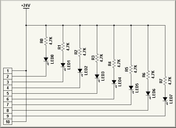
The DEWAR CONNECTED STATUS BOARD contains simple set of eight LEDs. Each LED's anode is tied to the +24V power supply via a 4.7 K resistor. The cathode is wired to a pin on the board's only connector, J1. J1 is then wired to the CABLE CONNECTED signals via J2 of the EL-5010 Quad Current Source boards. Thus, when a dewar is connected to one of the input channels the appropriate LED is illuminated.