Dewar Monitor System Electronics
Block Diagram,  EL-5009
Schematic: schematics\DMS_block.pdf
Page last updated: September 29, 2011
Simplified Drawing
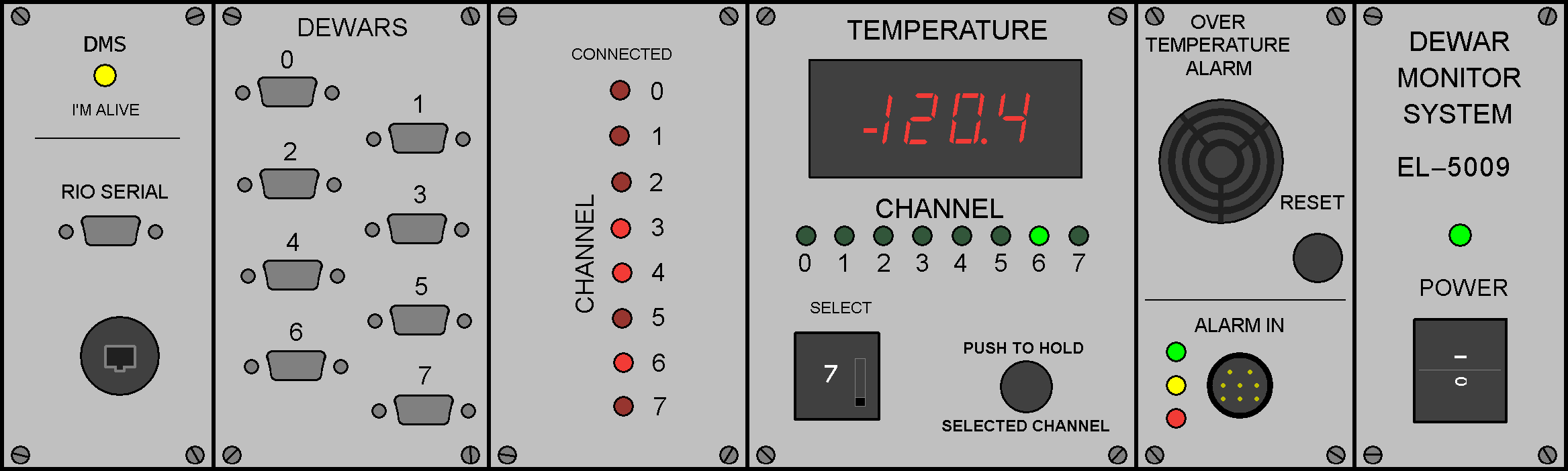
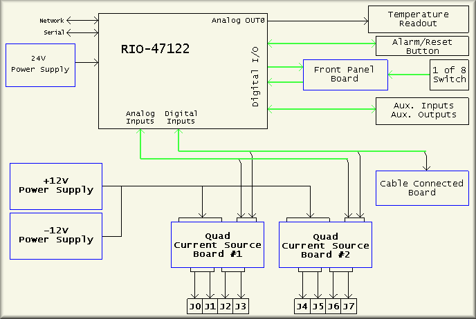
The DMS block diagram schematics shows the working components of the system without getting into wiring details. The main block in the diagram is of the Galil RIO-47122 I/O controller. The RIO is powered by the 24V power supply shown on the left. Note that the 24V supply is the reference for all of the digital I/O. The+12V and -12V supplies power the two current source/amplifier boards. The +12V is also used on the panel meter interface board to supply the LM7905C 5V regulator. (The meter requires +5V to run its logic. ) The analog output AO0 is used to display the temperature of the selected channel. The various other digital I/O lines are wired to the other blocks in the drawing. The main active components to the system are the two Quad I-Source and Amplifier boards. These boards are connected directly to the front panel DB9 connectors as shown at the bottom of the diagram. Each board has four constant current source circuits that are used for monitoring the temperature diodes of up to four dewars each. Each channel has been calibrated to provide a temperature derived from the 'standard' CCD Lab 1N914 diode as is used in all Lick dewars. Thus, any dewar can be attached to any input channel and the temperature readings should be very close to what the dewar's actual temperature is. Remember however, the DMS is not controlling the temperature of the dewar so it will likely read lower than you would expect in normal operation. Also important, calibrating the channels make each unique in that the slope and offset values are different for each signal chain. These values are burnt into the RIO's program. Thus, the two boards are not interchangeable. The Quad I-Source and Amplifier boards also pass the dewar connected line from the dewars to the RIO's digital input DI0-7 and to the Cable Connected board/panel. On the diagram below the Temperature Readout block is the alarm and reset button block. This represents the Sonalert and the reset pushbutton switch. The Sonalert is triggered when any of the inputs are seen to rise 10° C above the dewars stored coldest temperature. Once triggered, the operator can refill the dewar with LN2 and then push and hold the reset button for at least 4 seconds to reset the alarm. However, the more pragmatic way to deal with the alarm is to:
- Note which channel(s) are warming up - note that the green LED will be flashing rapidly
- Turn off the DMS power switch (to quiet the alarm)
- Refill the dewar(s) that had warmed up
- Turn the DMS box back on
- Be sure to watch temperature display for each active channel to make sure that all channels are cold or cooling
The next block below the alarm/reset block is the Front Panel block. This board connects to the RIO, the 1-of-8 paddle switch and the 'PUSH TO HOLD' switch. Its primary function is to control the green 'CHANNEL' LEDs. These LEDs are driven by the RIO's digital output DO0-7. They are turned on as the RIO reads and processes the analog input from any attached dewar. Processing the input takes only milliseconds so a dwell time, controlled by the parameter CYCL, is used to allow the panel meter to 'settle' to the correct temperature. This of course allows the operator time to see the reading too. CYCL is currently set for 2.5 seconds. The RIO as flashes the green channel LED to indicate that that channel has warmed up. The 1-of-8 paddle switch can be set to view a single channel. To do so, the operator selects the channel of interest and then pushes and holds the aptly named "PUSH TO HOLD SELECTED CHANNEL" pushbutton switch. Doing so stops the normal cycling of the box and feeds the processed temperature of the selected channel directly to the meter.
The next block down represents three each auxiliary inputs and LED indicators. These are labeled as "ALARM IN" though they are all programmable to any future use needed. The CPC 8-pin connector provides connections for inputs DI13, DI14, and DI15 and supplies the grounds. The LEDs are driven, from top to bottom, by DO14, DO10, and DO12. While there is no code to handle the input, the three LEDs are set to illuminate when the "RESET" button is pushed but have no function at this point. Throughout the schematics, the only drawing that shows the connections is sheet 4 of the wiring diagram schematic.