APF Spectrograph Electronics
Analog Input Board,  EL-1230
Schematic: schematics\MULTIPURPOSE\ANALOG24.spdf
Page last updated: August 22, 2012
Simplified Schematic
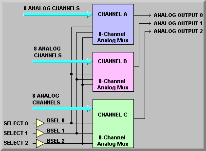
This board enables the Galil controllers to monitor up to 24 analog inputs. It was originally intended to connect to LM-35 temperature sensors but because we made it general purpose enough, it can be configured for other analog input signals as well. The board uses three 8-channel analog multiplexers to select one of eight inputs. The digital select lines come in on J1 pins 2, 4, and 6 and are buffered by the 74ALS35 buffer IC. They are wired to the address lines of G4 (sheet 1), G7, (sheet 2) and G11 (sheet 3). The outputs of the individual multiplexers are then wired to J1 output pins 9 (sheet 1), 11 (sheet 2), and 13 (sheet 3). The diagram above shows that we are looking at three inputs continuously and that when we change the select bits that we get three different inputs.
As mentioned above, these boards can be used to monitor several different types of inputs. The original use was for a temperature sensor supplying only a positive voltage output. It was soon discovered that it would be more useful to monitor both positive and negative temperatures. To this end, the circuit was modified by making certain parts optional.
Simplified Drawing
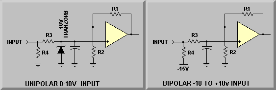
In the schematic on the left, the parts are selected for a unipolar input. This form is used for inputs from Renishaw encoders and other types of sensors that provide an analog output. Here, a 10V tranzorb is used to protect the amplifier from any spikes that might get onto the input. The gain of the stage, set by normal op-amp procedures, is selected to present a 0-10V signal to the analog multiplexer. The Renishaw encoder's status signal is a 0-5V signal so we set the gain for these inputs to A = 2. Other sensors are set accordingly.
The schematic on the right, show the configuration for a bipolar input. The temperature sensors are capable of negative outputs and thus, the circuit for them has the pulldown resistor tied to -15V. Also, the Tranzorb is removed from the circuit. The LM-35 sensors provide a 10mV/° signal that we amplify by a factor of 10 to give the Galil an input of 100mV/°. Thus, with an input of 0-10V we get a temperature reading of 0 to 100° C.
Simplified Schematic
Refer to the EL-1230 schematic for a more detailed discussion. On the lower left-hand side of sheet one is a DB-25 connector, J2. The connector has eight each +5 volt, Gnd, and input signal. The +5V and Gnd go to the LM-35 sensor and the input is the signal from it.
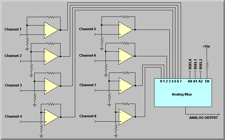
This sheet also contains eight amplifier circuits. The input channels are designated Channel nA where n is the channel number and A refers to the analog output at which the Galil can read the signal.
With the exceptions of channels 1C, 2C, 3C, 4C, and 7C (on sheet 3), the other input amplifiers can be set for a nominal gain of 10 via the input and gain resistors or they can be made bipolar by removing the tranzorb and connecting a pulldown resistor to the -15V supply. Using channel 1A, as an example R4, R5, and R6 set the gain of the amplifier to 10. A 10V tranzorb can be added across any unipolar input so that any over voltage won’t damage the op-amp. Note though that because of the board layout, this must be done in groups of four to accommodate the eight pin package of the SMDA-12. The output of the op-amp is sent to the LF13508NA analog multiplexer input S1 at pin 4. Again, the output of the analog multiplexer is connected to pin 9 of J1 and is read by the Galil controller at ANALOG IN 1.
Sheet 2 show the second bank of inputs on J3. The inputs, 1B through 8B, are multiplexed at G7 and the output is connected to pin 11 of J1 and is read by the Galil controller at ANALOG IN 2.
Sheet 3 is somewhat different from 1 and 2 in that five of the channels are hard wired to an onboard LM35 or the various power supplies. Thus, additional temperature sensors are wired via a DB-9 instead of a DB-25. Channel 1C is wired to the +5V logic supply. It is applied to op-amp G10 where the gain is set to 1. Thus the level of the supply is read directly by the Galil controller. Channel 2C monitors both the +15 volt and –15 volt logic supplies. This is done by selecting R69 and R70 to produce a voltage near the center of the range of the ADC input of the Galil controller. The gain of the op-amp is set to 1 by R71. This allows the controller to watch for changes in either supply by looking at just one input. Again, the input is protected by the 10V tranzorb. Channels 3C and 4C are setup to monitor the 28-volt servo motor supply. Though we only use one in this application, each of the inputs are attenuated by the combination of the input and gain resistors. The attenuation produces an output level near 5 volts, again in the middle of the Galil’s ADC input range. Channel 7C is hard-wired to an onboard temperature sensor. This sensor is used to monitor the ambient temperature at the board and thus, in the electronics locker in which it is mounted. The last three channels are again set for a gain of 10 for possible use of temperature sensors. The inputs, 1C through 8C, are multiplexed at G11 and the output is connected to pin 13 of J1 and is read by the Galil controller at ANALOG IN 3.