CCD Controller Overview
Block Diagram, ![]() EL-3160
EL-3160
SCHEMATIC: schematics/Block.sch.pdf
Block Diagram
OVERVIEW:
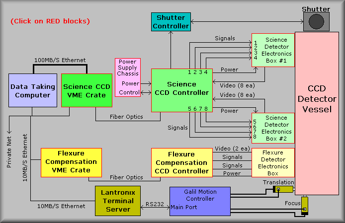
The block diagram above gives the technician a good feel for the interconnection of the two CCD systems on the DEIMOS spectrograph. At the top of the drawing are representations of the shutter and the Shutter Control Box. The Shutter Control Box is discussed in detail in the Miscellaneous Drawings section of the DEIMOS Spectrograph Electronics manual. Quickly, it converts the shutter open output from the CCD controller to the needed signals that control the two bladed shutter design employed by the DEIMOS instrument. The controller supplies a high (5V) DC level output when the shutter is open and a low (0V) level when the shutter is to be closed. The Shutter Control Box takes this signal and provides the correct pulsed solenoid output to sequence the two blades.
In the center of the drawing is a representation of the Science CCD controller signal chain. Starting at the dewar, there are two dewar electronics boxes. Each of the two interconnects four CCD devices with the controller. The electronics boxes each contain four Analog Switch boards, four Dual Preamplifier boards, and a power filter board. The electronics boxes connect to the CCD devices via hermetic connectors and to the CCD Controller as shown on the diagram. The CCD Controller performs the various functions of the system that include reading the CCD's, controlling the shutter, and sending the data to the CCD Crate. The size of the CCD mosaic dictated that the power supplies for the controller would have to be mounted external to the controller. Thus the power supply is shown as a different block. In using an external power supply, it was determined that the Power Monitor board would have to live in the external box. Finally, the CCD VME Crate communicates with the data taking computer and the CCD Controller. Communications to the controller are done with a set of duplex fiber cables and via a 100MB/sec Ethernet connection to the data taking computer.
Below the Science CCD signal chain is a representation of the Flexure Compensation System, or FCS CCD controller. The FCS system reads out two X00xX00 CCD devices that are mounted on opposite sides of the science mosaic. The FCS is used to compensate for flexure in the mechanics and optics of the spectrograph. To do so, a Copper-Argon lamp illuminates a pair of fiber optics, two per CCD, that are directed at the CCDs. The CCDs are read out and the images are processed to determine if any flexure is present in the system. If any is detected the control system will adjust the position of the tent mirror and/or the CCD Dewar translation stage to counteract the flexure.
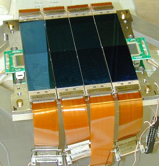
The FCS devices are located at each end of the centerline of the mosaic.
(Surrounded by green circuit boards)
Science Dewar Electronics box 1:
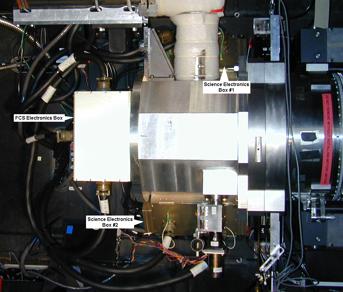
The science dewar electronics boxes are located on the sides of the dewar.
The electronics box that is mounted to the dewar contains four analog switch boards, four preamplifiers and a power filter board. Each of the CCD signal cables terminate into an EL-3192 board. This board contains the analog switches that are used to isolate the CCD device pins from the outside world. The output of these boards are hand-wired cables which terminate into a cable mounted 6-pin connector, which, in turn connect to the 61-pin hermetic connectors that are soldered into the dewar wall. The video signal coming back from the CCD is wired via three coax SMB connectors. Only the inner conductor of the SMB is used. Two of the SMB's are dedicated to the video signal and the third is used to provide an isolated ground connection between the CCD output and the preamplifier input. The idea is to keep the noise as low as possible between the CCD and pre-amp. The last board in the dewar electronics box is the power filter board. A set of 17-pin power cables are run from the CCD controller box and the dewar electronics boxes. These provide +5V, +16V, and -16V power to the analog switch board and the preamplifier board. The power filter board contains filtering and power distribution connectors for the other boards.
Science Dewar Electronics box 2: The electronics box that is mounted to the dewar contains four analog switch boards, four preamplifiers and a power filter board. Each of the CCD signal cables terminate into an EL-3192 board. This board contains the analog switches that are used to isolate the CCD device pins from the outside world. The output of these boards are hand-wired cables which terminate into a cable mounted 6-pin connector, which, in turn connect to the 61-pin hermetic connectors that are soldered into the dewar wall. The video signal coming back from the CCD is wired via three coax SMB connectors. Only the inner conductor of the SMB is used. Two of the SMB's are dedicated to the video signal and the third is used to provide an isolated ground connection between the CCD output and the preamplifier input. The idea is to keep the noise as low as possible between the CCD and pre-amp. The last board in the dewar electronics box is the power filter board. A set of 17-pin power cables are run from the CCD controller box and the dewar electronics boxes. These provide +5V, +16V, and -16V power to the analog switch board and the preamplifier board. The power filter board contains filtering and power distribution connectors for the other boards.
|
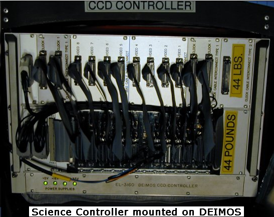
Science CCD Controller
|
||||
 |
 |
 |
||
|
Controller mounted in rack on DEIMOS
|
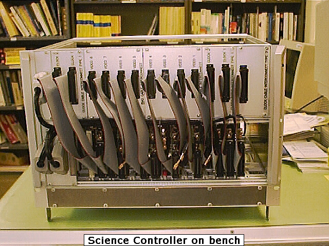
Controller on bench
|
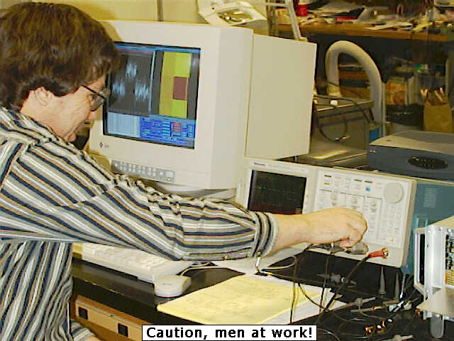
Chris Wright Testing controller
|
||
The science controller is a scaled up version of the FCS controller. It is a 16-channel controller that uses both Bob Leach's SDSU controller board set and the UCO/Lick support board set. The combination provides control of the eight 2Kx4K CCD devices and the transfer of the read out data to the Science VME Crate.
The CCD controller consists of at sixteen slot 3U VME P1 backplane, and the following boards:
- 1 ea. SDSU2 Timing board
- 5 ea. SDSU2 Clock Generator boards
- 8 ea. SDSU2 Video processing boards
- 1 ea. SDSU Utility board
- 1 ea. EL-3193 Utility support board
- 8 ea. EL-3194 61-pin Cable Interconnect boards
- 1 ea. EL-3195 Power and Miscellaneous Signal board
- 1 ea. EL-3197 Clock Cable Interconnect Type II board
- 2 ea. EL-3198 Clock Cable Interconnect Type I boards
- 2 ea. EL-3199 Bias Cable Interconnect boards
- 1 ea. EL-1198 Power Monitor board
At the heart of the controller is the set of SDSU boards that, under software control, generate the clocking waveforms and bias voltages for the CCD, digitizes the video output, and transmits it to the CCD crate. They also do the timing of the exposures, control the shutter, and control the temperature of the CCD mosaic. For more detailed information on the operation of these boards please see the software manual.
Note: the power supplies and the Power Monitor board are mounted in the Power Supply Chassis. (See below)
The controller connects to the two science dewar electronics box via the following set of cables:
| 1. Eight signal cables, one each for the eight CCDs. These cables contains: | ||
| • All of the clocks signals. | ||
| • All of the bias levels. | ||
| • Connectors are 61-pin MS style connectors. | ||
| 2. Two power cables, one for each of the two dewar electronics boxes. These cables contains: | ||
| • The power supply voltages. | ||
| • The Analog Switch Enable signal. | ||
| • Heater Resistor power. | ||
| • Temperature diode connections. | ||
| • Connector is a 17-pin MS style connector. | ||
| 3. Sixteen video (coax) cables, two each for the eight CCDs. | ||
| 4. One shutter control DB15 cable that connects to the shutter controller. | ||
The controller also connects to the VME Crate by way of a duplex fiber optic cable.
Science CCD Controller Power Supply: The complexity of the Science CCD Controller dictated that an external power supply box would be needed. This box was built into a 4U size chassis. The box contains a 12 ampere +5V supply, a 9 ampere +16V supply, a 9 ampere -16V supply, and a 800 milliampere 38V supply. The Power Monitor board is located in the power supply chassis and controls the application of the +/-16V and +38V supplies to the VME backplane. Because it was not designed to handle the 9 amperes of the +/-16V supplies, a set of relays was employed to switch these supplies on and off. The power supply chassis connects to the CCD Controller via two large cable. Each conductor for the supplies is 14 AWG wire to ensure the adequate current carrying capabilities. In the case of the chassis grounds, an 000 AWG wire was used. All supply sense lines are 18 AWG and the Power Monitor control and status signal wires are 20 AWG.
Science VME Crate: The Science CCD Crate lives in the computer room and consists of a chassis with a horizontal 5-slot VME cage, power supplies, and cooling fans. The card complement consists of a Motorola CPU card, a Chrislan 256MB Memory board, and a SDSU2 VME interface card. This box provides the link between the CCD controller and the instrument computers. It connects to the CCD controller via a duplex fiber optic cable and to the instrument computer via a private net. The box serves as a buffer and protocol converter between the CCD controller and the instrument computer. The SDSU2 VME interface card communicates with the CCD controller and under the direction of the CPU board stores the CCD image into the memory card. The CPU card then formats the data and sends it to the instrument computer via the private network.
FCS Dewar Electronics box: The electronics box that is mounted to the dewar contains two analog switch boards, two preamplifiers and a power filter board. Each of the CCD signal cables terminate into an EL-3192 board. This board contains the analog switches that are used to isolate the CCD device pins from the outside world. The output of these boards are hand-wired cables which in turn connect to the 61-pin hermetic connectors that are soldered into the dewar. The video signal coming back from the CCD is wired via three coax SMB connectors. Only the inner conductor of the SMB is used. Two of the SMB's are dedicated to the video signal and the third is used to provide an isolated ground connection between the CCD output and the preamplifier input. The idea is to keep the noise as low as possible between the CCD and pre-amp. The last board in the dewar electronics box is the power filter board. A set of 17-pin power cables are run from the CCD controller box and the dewar electronics boxes. These provide +5V, +16V, and -16V power to the analog switch board and the preamplifier board. The power filter board contains filtering and power distribution connectors for the other boards.
The FCS dewar electronics box is located at the rear of the dewar.
 |
 |
 |
||
|
FCS Front View
|
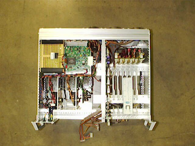
Top View
|
Rear View
|
The FCS CCD controller consists of a 6-slot, 3U VME P1 backplane, and the following boards:
- 1 ea. SDSU2 Timing board
- 1 ea. SDSU2 Clock Generator board
- 1 ea. SDSU2 Video processing board
- 1 ea. SDSU Utility board
- 1 ea. EL-3193 Utility support board
- 2 ea. EL-3194 61-pin Cable Interconnect boards
- 1 ea. EL-3195 Power and Miscellaneous Signal board
- 1 ea. EL-3198 Clock Cable Interconnect Type-1 board
- 1 ea. EL-3199 Bias Cable Interconnect board
- 1 ea. EL-1198 Power Monitor board
At the heart of the controller is the set of SDSU boards that generate the clocking waveforms and bias voltages for the CCD, digitizes the video output, and transmits it to the CCD crate. They also do the timing of the exposures, control the shutter, and control the temperature of the CCD. For more detailed information on the operation of these boards please see the software manual.
The UCO/Lick boards perform the following functions:
The FCS controller is a two channel controller that uses both Bob Leach's SDSU controller board set and the UCO/Lick support board set. The combination provides control of the two CCD devices and the transfer of the read out data to the FCS VME Crate. The controller connects to the FCS dewar electronics box via the following set of cables:
| 1. Two signal cables, one each for the two CCDs. These cables contains: | ||
| • All of the clocks and bias levels | ||
| • Connectors are 61-pin MS style connectors | ||
| 2. A power cable. This cable contains: | ||
| • The power supply voltages | ||
| • The Analog Switch Enable signal | ||
| • Heater Resistor power | ||
| • Temperature diode connections. | ||
| • Connector is a 17-pin MS style connector | ||
| 3. Four video (coax) cables, two each for the two CCDs. | ||
The controller also connects to the VME Crate by way of a duplex fiber optic cable.
FCS VME Crate: The FCS CCD Crate lives in the computer room and consists of a chassis with a horizontal 5-slot VME cage, power supplies, and cooling fans. The card complement consists of a Motorola CPU card, a Chrislan 256MB Memory board, and a SDSU2 VME interface card. This box provides the link between the CCD controller and the instrument computers. It connects to the CCD controller via a duplex fiber optic cable and to the instrument computer via a private net. The box serves as a buffer and protocol converter between the CCD controller and the instrument computer. The SDSU2 VME interface card communicates with the CCD controller and under the direction of the CPU board stores the CCD image into the memory card. The CPU card then formats the data and sends it to the instrument computer via the private network.