CCD Chassis Wiring
Interconnection Diagram, ![]() EL-3161
EL-3161
SCHEMATIC: schematics/Intercon.sch.pdf
The EL-3161 schematic lays at the heart of the DEIMOS Science CCD controller. This diagram shows the integration of the signals from both Bob Leach's SDSU Generation 2 controller board set and the UCO/Lick Observatory auxiliary boards and wiring.
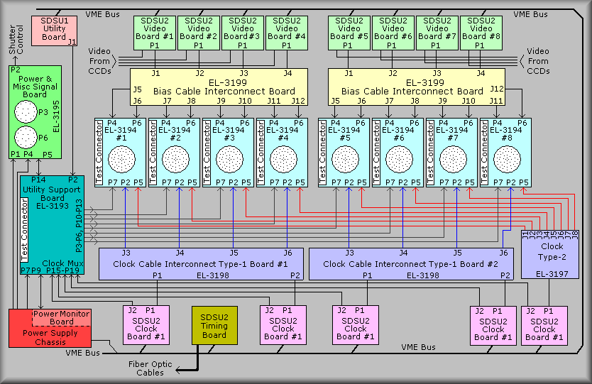
The set of boards in the middle of the diagram represent the 61-pin Cable interconnect boards. There are one of these cards for each CCD device in the dewar. These boards perform three major functions:
In addition to these functions, the board also provides a test connector that makes all signals available to probe with an oscilloscope, and it contains a selection of jumper posts for easy configuration of various signals - including spare bias inputs.
Above the EL-3194 boards are the EL-3199 Bias Cable Interconnect boards. These boards interconnect the SDSU bias levels to the EL-314 board. The diagram shows that interconnect board has two output connectors for each input connector. This board divides the 24 incoming bias levels into two sets of 12 outputs. This scheme allows us to configure the controller to run either one or two amplifiers per CCD. In initial testing, the system was run in single amp mode using just 4 video boards. Later, four more video boards were purchased for the system and the only change needed in the controller hardware was to reconnect the existing 14-conductor ribbon cables and eight more. The time needed to make this change (speaking only of the hardware!) was about 1 day.
At the top of the drawing are boxes that represent the 8 video boards and to the extreme left, the SDSU Utility board. Note that Utility board is a generation 1 board. The heavy line at the top edge of the diagram represents the VME backplane. Though the backplane is a VME standard backplane, the SDSU boards redefine the connections over it and thus is not compatible with the VME standard. It continues around the right edge of the diagram and to the bottom edge. The lighter lines entering the video boards at the bottom are the two video coaxes that connect to the output of the pre-amps in the dewar electronics boxes.
The SDSU Utility board connects most of the I/O from the SDSU boards to the rest of the controller. The connector J1 is a 96-pin euro-din connector. The 64-pin cable (the 'B' row is not used) connects to the Lick Utility Support board.
To the left and just below center is the EL-3193 Utility Support board. It's purpose is to interface the SDSU system to the 'outside world'. Lick has designed this board with a 96-pin connector, P2, to receive the signals from the Utility board and a second 96-pin connector that faces out the front of the board. This connector pin-for-pin duplicate of the input connector and is used as a set of test points to aid in troubleshooting. P14 of the support board connects the shutter, heater control, and temperature monitoring signals to the EL-3195 Power and Miscellaneous Signal board. P3 through P6, and P10 through P13 connect auxiliary heater control, auxiliary temperature readout, bias select lines, and a multiplexed bias input signals. The bias select lines allow the control software select each bias level generated in the video boards to be read back for comparison with the intended value. A multiplexer located on the EL-3164 board is controlled by the bias select lines and the output - one of twelve bias levels - is routed back to the Utility Support board where they are routed to another multiplexer. This multiplexer is uses a set of CCD SELECT control lines to select one of up to eight possible CCD chains connected to the controller.
In a similar fashion, the connectors P15 through P19 connect to each of the SDSU Clock boards. The control software can direct any one of the clock waveforms to the clock board's output SMA connector. The other end of these cables are connected to the Utility Support board where, again, they are routed to a multiplexer. Using the same CCD SELECT control lines, the software can now look at each of the clock waveforms.
The connector P9 is wired to the Power Monitor board. These connections allow the software to control the +/-16V power supply outputs that feed the VME backplane and control the analog switches that apply voltages to CCD. The normal operation is to first setup the desired bias levels and clock waveforms, then turn on the +/-16V supplies, next, turn on the +38V supply, and finally, turn on the analog switches. The process is repeated in reverse to power down the CCDs. The Power Monitor board also controls the EXRSET, external reset, line going back to the SDSU Utility board. This line will be asserted if the +5V supply is drawn down below about 4.6 volts.
P7 on the Utility Support board provides +5V and +/-16V to the board.
Above the Utility Support board on the diagram is the EL-3195 Power and Miscellaneous Signal board. This board provides power for the dewar electronics boxes, routing for the analog switch enable signal, and a connector for the Lick EL-1183 Shutter controller. This board contains no active parts. It does, however, supply several posts connected to spare wires in the 17-pin power cables that route power to the electronics boxes.
Below the EL-3194 boards on the diagram are two Type-1 and one Type-2 Clock Cable Interconnect boards. The Type-1 boards accept two sets of 24 clock lines from the SDSU Clock boards and break them into 4 sets of 12 clock. Again, this allows use to the boards in various configurations. The Type-2 board breaks bown the 24 clocks into eight sets of three. This allow us to add a second set of parallel clocks for devices that allow them.
The set of boxes at the bottom of the schematic represent the remaining SDSU Clock boards and the SDSU Timing board.