Miscellaneous Drawings
Gurley Index Finder Test Fixture, ![]() EL-1299
EL-1299
Schematic: schematics/Multipurpose/GUR_INDEX_TEST.sch.pdf
Page last updated: May 14, 2002
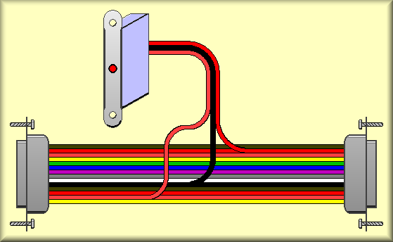
This diagram shows the Gurley encoder index finder test fixture. The test fixture is used to locate the Index pulse on the encoder. Because of the very short duration of the pulse, it is very hard to see on an oscilloscope or other piece of test equipment. The fixture uses the native index pulse to fire a one-shot that drive and LED that gives the technician a very good approximation of the location of the pulse. On the two stages that use Gurley encoders, grating tilts 3 and 4, the visual signal is precise enough for adjusting the encoder's position. The procedure for using the test fixture is to disconnect the cable that runs from the Gurley Interpolation amplifier and the stage interconnect box. The test fixture is then connected in series with that cable. With the stage/controller power on and the encoder physically out of the system, the shaft of the encoder is rotated while watching the LED. When the index is encountered, a match mark is made on both the encoder body and shaft. (These marks are already on the existing encoders.) In the case of the grating tilts, lining up the match marks is sufficient to be within range of the control software's ability to zero on the index. The difference between the stage zero point (fiducial) and the Gurley index pulse is mapped by the software group and then used for offsetting to the index pulse. This should point out that if the encoder is removed and reinstalled into the stage this distance must be re-mapped.