Cradle Wiring
The cradle stage wiring section of this manual contains descriptions of the rotation stage wiring and associated systems for the cradle portion of the DEIMOS Spectrograph. It corresponds to the Cradle Stage Wiring tab in the electronics schematics binder.
Shuttle Drive System, ![]() EL-3123
EL-3123
Schematic: schematics\SHUTTLE.sch.pdf
Page last updated:
February 19, 2003
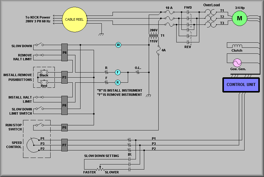
Simplified Drawing
The above drawing show the wiring for the 'tractor' that moves
the DEIMOS instrument in and out of the elevation baring on the Nasmyth platform.
The motor is show at the top, right corner of the drawing. When not in a limit
or in 'slow down' mode, the Install/Remove pushbuttons control the
movement and direction of the motor. As the note in the center of the drawing
suggests, the reverse direction on the motor moves the carriage into the telescope
baring and the forward direction moves the carriage away from the baring. The
end of travel limit switches are labeled Remove Halt Limit for removing
the carriage and Install Halt Limit for installing the instrument into
the baring. The motor speed is controlled by the Run/Stop switch and
the Speed Control rheostat in the lower, left hand corner of the drawing.
The Run/Stop switch control the 115 VAC control circuitry. In the Stop
position the 115V is not available to supply either the F,
R or IR relay coils. Without power, the FWD
and REV contactors can not supply the 208 VAC power to the
motor. When power is turned on the direction contactors are controlled by the
F and R coils. The coils are in turn controlled
by the Install and Remove pushbuttons on the control paddle.
Note that when one button is pushed it breaks a contact in series with the opposite
direction pushbutton.
The speed at which the motor, and thus, the carriage move is determined by one
of two rheostat settings. The IR relay coil (Internal
Rate) in the upper center of the drawing controls wheether
the motor runs at the speed setting of the control paddle or at it's internal
setting. The contacts of the IR relay are shown at the bottom, center of the
drawing. The internal rate is called Slow Down Setting on the schematics.
The IR relay is energized whenever one of the Slow Down
Limit switches are activated. These limit switches are set several inches
in front of the normal end of travel limit switches. Thus, the carraige will
slow down before it reaches either limit. The actual speed control is handled
by an Eaton #15-47 Control Unit. This box applies the voltage to the motor and
actuates the clutch.