Cradle Electronics
The cradle electronics section of this manual contains descriptions of the cradle electronics for the DEIMOS Spectrograph. It corresponds to the Cradle Electronics tab in the electronics schematics binder.
Overall Diagram Of Cradle Electronics, ![]() EL-3100
EL-3100
Schematic: schematics/VLTSERVO.sch.pdf
Page last updated:
February 3, 2003
Extra info: ![]()
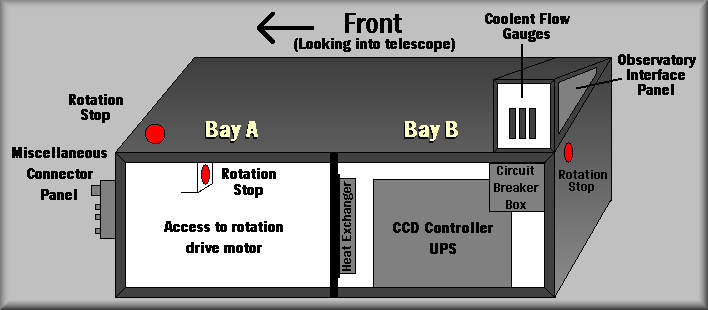
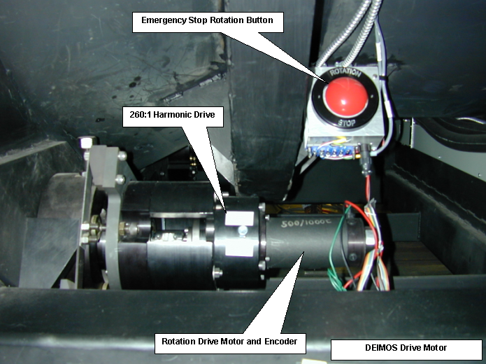
Bay A |
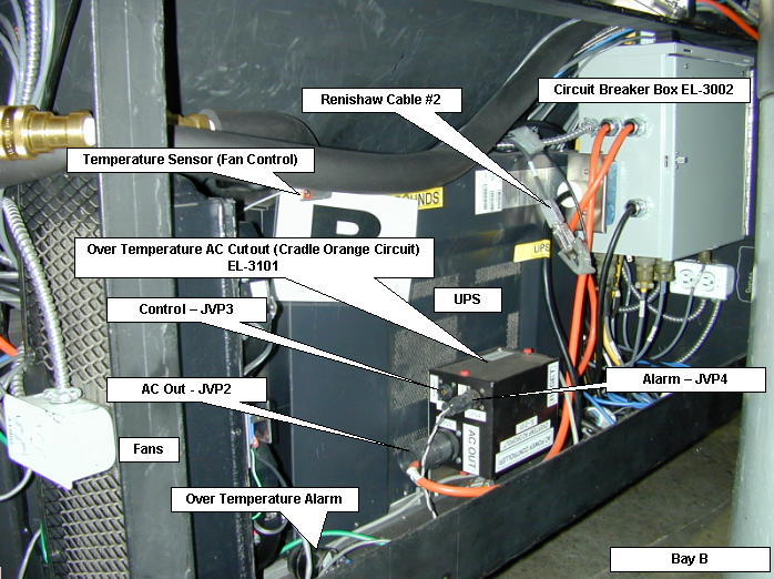
Bay B |
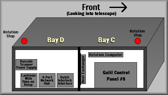
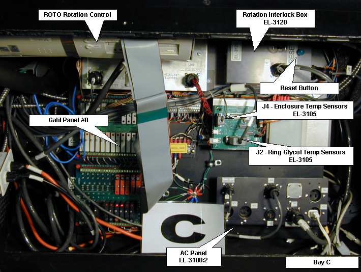
Bay C |
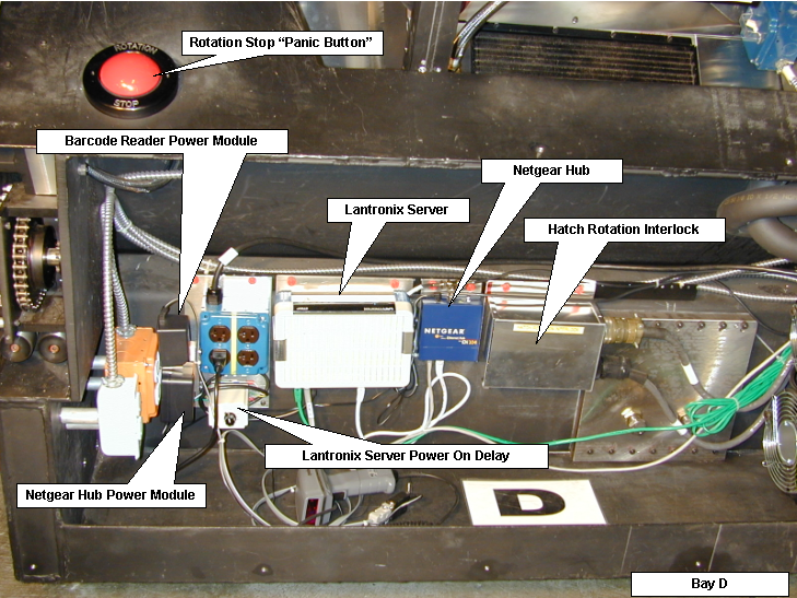
Bay D |
 |
 |
 |
 |
| Click image for larger
picture |
|||
Simplified Diagram
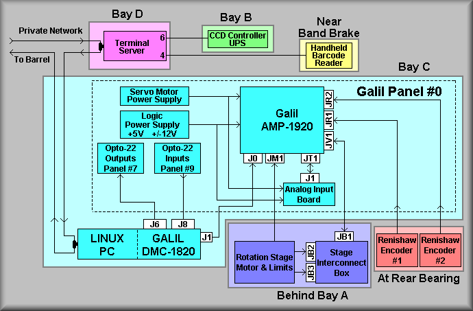
The above diagram is a representation of the overall cradle electronics for
the DEIMOS instrument. Note that the background color in each of the blocks
is different. The different colors represent different areas of the instrument.
For example, the light blue color represents the 'C' bay and the light green
background represents the 'B' bay of the cradle The left top of the diagram
shows the 'private network' coming into the instrument. This network is used
to communicate between the instrument computer and the instrument electronics.
This 10base2 cable provides control and status that is not available to the
outside world. The instrument elements that use this network are the rotation
Linux PC, the two Lantronix terminal servers. The local terminal server is
currently connected to the CCD controller UPS and the handheld barcode scanner
that is used to identify the removable spectrograph elements - filters and
slitmasks.
In the blue box, the private network connects to the Linux PC. Again, this
connection allows the PC to communicate with the instrument controller. In
particular, the rotation computer talks to the DS9 software to sync the DEIMOS
instrument rotation to the motion of the telescope. The PC has a Galil DMC-1820
servo motor controller card installed to control the instrument rotation.
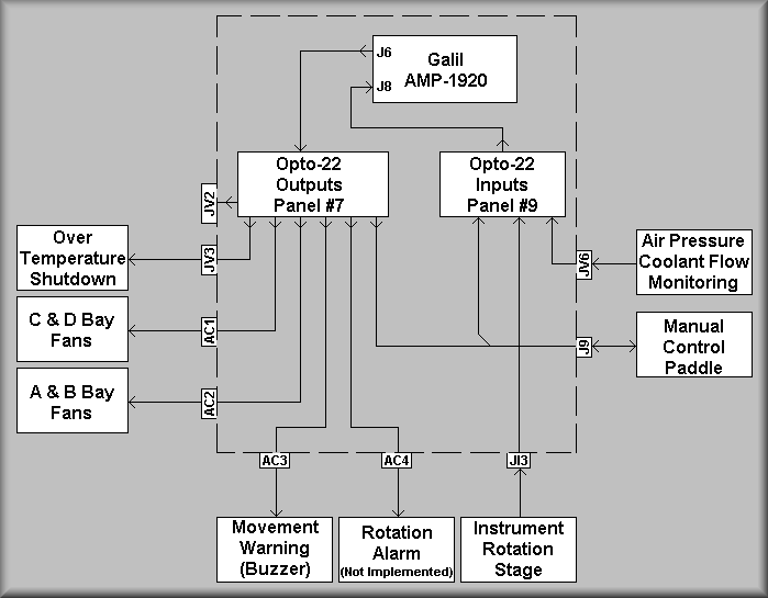
J6 and J8 on the co0ntroller card are wired to two 24-channel Opto-22 relay
racks. As seen above, one card is used for digital inputs and the other for
digital outputs. This I/O is used to control and monitor many functions on
the instrument cradle (See EL-3113
and EL-3115 for more details.)
The Galil AMP-1920 block represents not only the amplifier but also a set
of connectors mounted to the amplifiers. These connections include the following:
Simplified Diagram
Simplified Diagram
Simplified Diagram
Simplified Diagram