Barrel Stage Wiring
The barrel stage wiring section of this manual contains descriptions of the individual stage wiring for the barrel portion of the DEIMOS Spectrograph. It corresponds to the Barrel Stage Wiring tab in the electronics schematics binder.
Grating Clamp Stage,
![]() EL-3082
EL-3082
Schematic: schematics/GRATCLMP.sch.pdf
Page last updated: October 29, 2003
Simplified Drawing
Some terms:
In the following discussion I will be using the following terms.
Drawing Description:
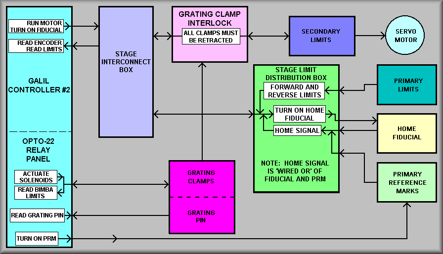
The above drawing shows a block diagram for the grating
clamp stage. The grating clamp stage is, in fact, different then the grating
tilt
stages.
The purpose of the grating clamp stage is to clamp the selectable grating
cells
into the grating box. The grating box is the stiff structure
that positions the grating cell in the beam. The grating clamps then are
applied to hold
the cell to the grating box. The cyan box on the left side of the diagram
denotes Galil controller #2. The controller commands the grating slide mechanism
to move the various cells into position for clamping. The lower portion of
the Galil block shows the Opto-22 I/O functions. (Sheet 2 gives more details
for the I/O) To the right of the Galil block is the stage interconnect box
(in violet). This is a standard interconnect box that provides terminal strips
for probing signals and a mount for the EL-2260 encoder buffer board. To
the right of this block is a pink block that represents the interlock box
for the grating slide stage limits. The magenta block in the lower, center
of the diagram represents the set of 4 pneumatic cylinder clamps. The bright
green block represents a box that acts as a limit switch mixer.
The mixer brings together many of the various limit signals to send
back to the controller. The light green box in the lower right corner represents
the Primary Reference Mark for the grating clamping position. The other
boxes represent the normal motor, primary limits, secondary limits, and fiducial
for the grating translation stage. These are all discussed in the EL-3066 write
up.
Overview of operation:
The overall operation of the grating translation stage and grating clamp
stages works as follows. Assume that a grating cell is in position and
the observer
wants to change to a different grating. The order in which the new
grating
is moved into position is:
Detailed descriptions:
In the diagram above, the white insets display the critical functions for
stage operation. Starting with the Galil controller block on the left side
of the sheet, before any move will be attempted in software, all of the
grating translation stage limits must be in the no limit condition.
Further, before a movement will be attempted, all four of the grating clamps
must be in the retracted position. If any of these conditions are not met,
the controller will generate an error that will be sent back to the control
computer.
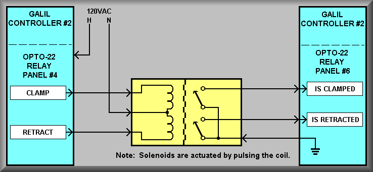
At this same time, the controller will turn on the PRM. The PRM is mounted
on the non-moving portion of the grating box and interacts with a blade
attached to each of
the grating cells.
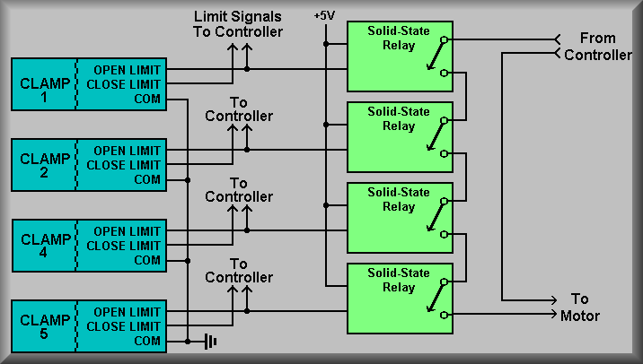
The Grating Clamp Interlock block on the drawing represents a
series of four Crydom solid-state relays that are wired in series with
one side of
the motor power. If any one of the grating clamps is not retracted the
relay will open and cause the motor to stop. As implied, each of the relays
is accuated by a limit switch that senses that the pneumatic clamp is in
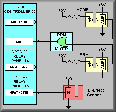
the fully released position. The Grating Pin is a seperate hall-effect
limit switch that works in concert with the grating clamp limits by sensing
that the
grating
cell
is clamped correctly into the grating box.
The Stage Limit Distribution Box is a metal box that is attached
to the stage interconnect box. It's purpose is to collect many of the various
limit input and
Simplified Drawing
Simplified Drawing
Simplified Drawing