Barrel Stage Wiring
The barrel stage wiring section of this manual contains descriptions of the individual stage wiring for the barrel portion of the DEIMOS Spectrograph. It corresponds to the Barrel Stage Wiring tab in the electronics schematics binder.
Entrance Hatch Stage,
![]() EL-3080
EL-3080
Schematic: schematics/HATCH.sch.pdf
Page last updated: May 14, 2002
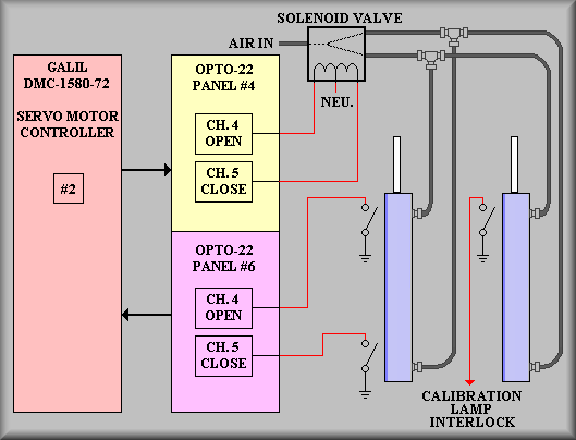
Hatch stage simplified drawing
The entrance hatch stage consists of a Honeywell control solenoid, two Bimba pneumatic cylinders, three Bimba position/limit switches and the control I/O. As seen in the simplified drawing above, one I/O bit is used to open the hatch and another is used to close it. The solenoid valve directs air either into the front end of the cylinder or the rear end of the cylinder. The position/limit switches are attached to the outside of the cylinders with their own mounting bands. The switches are adjusted by loosening the band, moving the switch, and then re-tightening the band. On the left-hand cylinder above, are the opened and closed position/limit switches. These feed back via the I/O rack to the motor controller and from there is available to the control computer. A third position/limit switch is mounted on the right-hand cylinder that acts as an interlock for the calibration lamp. This safety measure is intended to turn off the potentially damaging lamps if someone intentionally or accidentally looks through the hatch at the inside of the instrument.
The full schematic shows the wiring for the solenoid and position/limit switches. The hatch is opened and closed by Galil controller #2 via I/O channel 4 to open and 5 to close (I/O bits 29 and 30 of panel #4.) The position information is read back on channels 18 and 19 of panel #6 (I/O bits 91 and 92 of panel #6.) The solenoid for the hatch is mounted on the same panel as the solenoids for the grating system on the front face of the instrument drive disk. As shown on the schematic, stage control is wired via connector J43 on Galil panel #2 to JG43 on the solenoid panel. JG43 is wired to the terminal strip on that panel and then to the solenoid. The solenoid is manufactured such that a 50ms pulse to one side will cause the air to flow from the input port to one of the two output ports. At this point the solenoid mechanically 'latches' in that position (the air pressure holds the valve in this position.) A pulse to the other side of the solenoid will then cause airflow to change to the opposite output port. The Galil control software generates these pulses in normal operation. Note: this action requires air pressure to be applied to the inlet port of the valve body in order to latch. When troubleshooting, remember to apply pulses not levels. The obvious advantage to this type of solenoid is that power normally off and is only applied as 50ms pulses. This results in essentially no heat being generated. The third switch on the schematic is used to interlock the calibration lamps to the hatch. Details are available on the calibration lamp page.