Barrel Stage Wiring
The barrel stage wiring section of this manual contains descriptions of the individual stage wiring for the barrel portion of the DEIMOS Spectrograph. It corresponds to the Barrel Stage Wiring tab in the electronics schematics binder.
Slitmask Stage,
![]() EL-3067
EL-3067
Schematic: schematics/SLITMASK.SCH.pdf
Page last updated:
January 23, 2003
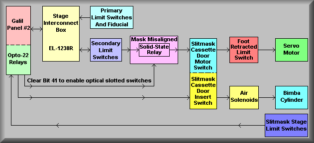
Slitmask system block diagram
The above block diagram shows the various components and signal flow for the DEIMOS Slitmask system. The stage actually consists of two functions: the servo motor portion runs the 'scissors jack' that positions the slitmask cassette to any of 13 positions and the Insert/Retract piston that moves the slitmask out of the cassette and into the slitmask form. The slitmask form refers to the machined frame into which the slitmask is inserted. The form is machined such that when the slitmask is fully inserted it is forced into the correct curved shape to match the focal plane. Galil controller #2, in the pink box at the left, operates the stage via a normal Stage Interconnect box (yellow box) and Expansion I/O (light green box). The 'Primary Limit Switches and Fiducial' box indicates that the servo motor stage operates like other stages in that the stage is homed with the home fiducial and normal motion will be stopped if either of the primary limits are tripped. However, the long signal path from the stage interconnect block (yellow) to the motor block (dark green) indicates that this stage is much more complex than most others. In order to actually drive the motor the Secondary Limits must not be made (lavender box), the Slitmask slotted optical switches must be enabled (Bit 21 cleared) and in the correct state (purple box), the Slitmask Cassette Door must be closed (blue box), and the Insert/Retract piston (red box) must be retracted. Only when all of these conditions are meet will there be a current path to the servo motor. To operate the Bimba cylinder Insert/Retract piston (medium yellow box), the controller toggles I/O bits on the Opto22 panel (light green box attached to the Galil controller). These signals also pass through the Slitmask Cassette Door switch(dark yellow box) and will only operate the cylinder when the door is closed. The dark blue box in the lower left hand corner indicates that each of the limits that can disable motion on the stage is also read back to the controller via the Opto22 I/O relays. Also, there are some limits that don't disable movement but are feed directly to the controller where the software determines if it is safe to move the stage. An example of this is the IN and OUT limits on the Insert/Retract limit.
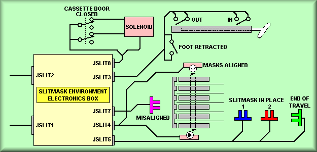
Simplified drawing
This sheet gives a graphical depiction of the connections from the Slitmask Environment Electronics Box to the various additional limits on Slitmask stage. The connectors JSLIT1 and JSLIT2 connect the box to Galil Controller #2 via Opto22 panels #4 and #5 respectively. Starting at the top of the drawing, JSLIT8 connects to the Insert/Retract solenoid via the Cassette Door limit switch. The solenoid has a latching mechanism that uses the air pressure through it to hold it in position. Thus, to operate the piston, a 20 msec pulse is applied to the desired coil - extended or retracted. And again, the Slitmask Cassette door must be closed before the piston will move. JSLIT3 connects to the limit switches that are activated by the Insert/Retract piston. Mounted on the Bimba cylinder are a pair of magnetic limit switches that are closed when the puck that is moved by air pressure is moved to either end of travel. This tells the controller that the mask is either fully in the cassette or extended into the slitmask form. Also wired to JSLIT3 is the Foot Retracted switch. This switch is activated by the physical stage that the slitmask 'foot'. The 'foot', represented by the white piece at the end of the cylinder above, is a machined shape that matches a similarly shaped hole on each of the slitmasks. This is the part that actually contacts the mask to move it in or out. JSLIT7 is wired to the Mask Misaligned optical switch. Looking at the gray representation of the end of the cassette, the slitmask's are represented by the thin black lines between the gray pieces. The gray piece at the left is refereed to as the 'comb'. It is spring loaded and is moved out of position if any of the masks are not located correctly within the cassette. JSLIT4 is connected to the two piece Masks Aligned sensor. This sensor is comprised of an IR LED and an IR detector. Each slitmask is machined with a hole located such that when it is seated correctly in the cassette that hole will line up with beam and the detector on the other side of the cassette will be turned on. JSLIT5, at the bottom of the diagram is connected to the last three optical slotted switches. The Slitmask In Place 1 and Slitmask In Place 2 sensors are used by the controller to tell conclusively if the slitmask if fully inserted. (see the limits in relation to a slitmask below) The end of travel slotted switch is mounted at the extreme end of the slitmask form and is only tripped when a mask it inserted and seated correctly. As mentioned above, to enable the optical slotted switches and the Masks Aligned sensors, the software must clear Bit 41

Simplified drawing
The servo motor portion of the slitmask stage controls the movement of a 'scissors jack'. The diagram to the left gives a simplified look at the scissor jack assembly. To move a slit mask into the deployment position, the jack is commanded to the appropriate position as determined by the motor encoder value. The main stage cable for the system is the same standard cable used throughout DEIMOS and connects the Galil controller/amplifier to the Stage Interconnect box.
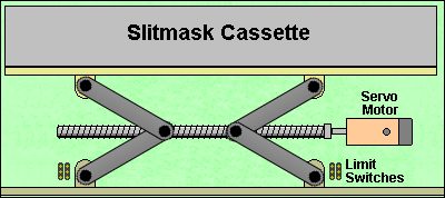
1. DC servo motor with integral optical disc encoder 2. Slotted optical switch that is used as the fiducial 3. Forward and reverse primary limit switches 4. Forward and reverse secondary limit switches
Stage Homing
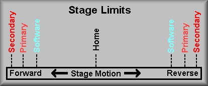
Stage Limits
These are shown on the drawing as the FLSE ( Forward Limit Switch channel E) and the RLSE ( Reverse Limit Switch channel E). Their function is to stop the motion of the stage if they are activated. These are inputs to the motion controller that causes the controller to stop any further movement in that direction. It will, however, allow you to move back out of that limit. Notice that to get to these limits the stage has already violated the software limits. The secondary limits are there to prevent physical harm to the stage. These limits are DPDT switches that perform two functions. First, one pole of the switch is wired in series with one pole of the motor. When the switch is activated the power to the motor is cut off. THIS MEANS THAT THE STAGE MUST BE DRIVEN OUT OF THESE LIMITS BY HAND. At this point, the stage requires manual intervention for the safety of the stage. The second set of contacts are wired to supply a signal to the controller that the limit has been tripped. This signal is fed to the controller input IN9 on pin 37 of the amplifier terminal strip. Because the forward and reverse switches are wired in series, this input does not contain information as to which direction the stage was traveling, just that it is in a secondary limit. Again notice, to get to this limit both the software and primary limits have failed.
Though the simplified drawing above does not show the stage interconnect box, the schematic does. It is important to note that the connectors to the interconnect box must all be plugged in to operate the stage. The limits are all wire via Normally Closed terminals on the switches. If a cable is disconnected the controller recognize the limit inputs as being active thus not allowing that stage to move.
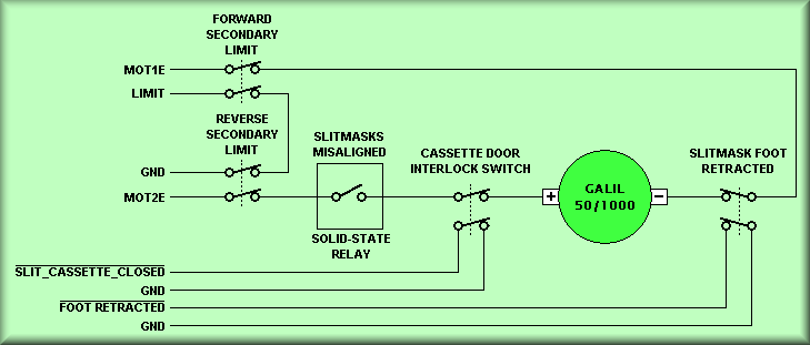
Simplified drawing
This drawing shows the additional limits in the slitmask stage servo motor
wiring. At the top, left, are the normal motor secondary limit switches. These
work in the normal way; if the stage moves into a secondary limit the only way
to move out is to rotate the motor shaft by hand. Next, the 'Slitmasks Misaligned'
solid state relay interrupts the current flow to the motor. The 'Slitmasks Misaligned'
sensor is a optical slotted switch which is not suitable for interrupting the
motor current. Thus, it is used to trigger a solid state relay. The 'Slitmasks
Misaligned' sensor verifies that none of the slitmasks are 'hung-up or not properly
seated in the cassette. Next in line is the cassette door interlock switch.
This switch is open whenever the door on the cassette (not the instrument
exterior access panel), is open. this keeps the stage from moving when the user
is loading or unloading slitmasks. The last limit switch is the 'Slitmask Foot
Retracted' limit switch. This switch is located such that the limit is open
any time the Insert/Retract piston is not fully retracted. Thus, the motor can
not move unless the foot is retracted indicating that the foot is clear of the
shaped cutout in each of the slitmasks.
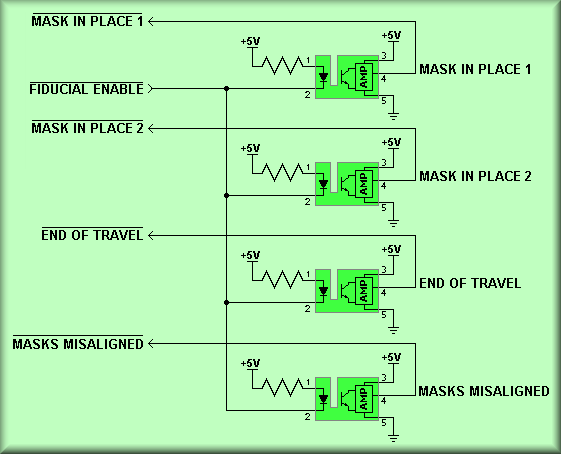
Simplified drawing
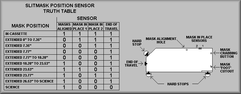
The above block shows details of the optical slotted switches used by the software to determine that a slitmask is in the proper place. Below is a view of a slitmask inserted into the Slitmask Form. The hard stops define the correct positioning of the slitmask while the various sensors are read by the software to confirm complete insertion of the mask.
Slitmask Limits and Hard Stops
Simplified drawing
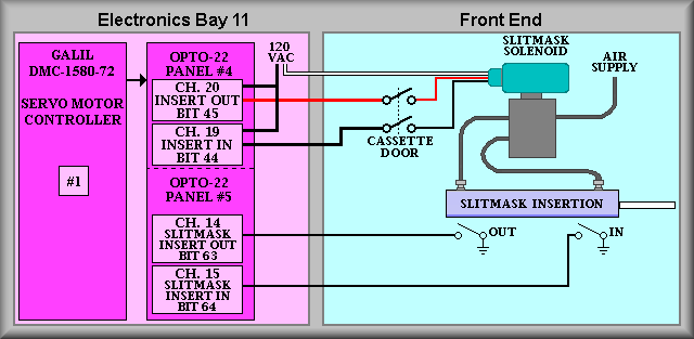
Sheet 5 details the connections to the slitmask Insert/Retract cylinder. Opto22 output channels 19 and 20 are used to command the cylinder into the desired position while input channels 14 and 15 are used to monitor the cylinder.'s position. As is the case with all pneumatic stages on DEIMOS, the solenoid used is a latching solenoid. This means that once the solenoid is set to direct the air to either of the output ports, an over center mechanism uses the air pressure to keep it in place. We drive the solenoid with a 20 uSEC pulse to toggle between states. Thus, the solenoid is only energized for the 20 mSEC and other then when it is actually changing states it doesn't dissipate heat. The 120 VAC coil solenoid is pulsed by channel to insert the mask and channel 19 to retract it. The outputs from these channels are wired via the Slitmask Cassette Door switch so that the solenoid will only toggle positions when the door is closed. The Bimba end of travel limit switches are wired back to input channels 14 and 15 and tell the software wheather the slitmask 'foot' is inserted or retracted. The cassette door limit switch, slitmask solenoid, and the slitmask Bimba cylinder are all located at the front of the instrument.
Simplified drawing
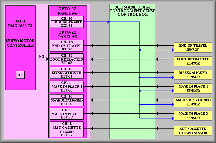
Sheet 6 shows the expansion I/O used by the slitmask stage. At the top, output bit 16 of Opto22 panel #4 is used (cleared) to enable the optical slotted switches and the IR LED used for the mask alignment holes. Note that the 'Foot Retracted' and 'Slit Cassette (Door) Closed' sensors are actual limit switches and don't need to be enabled. The software checks the status of each input, at the indicated bit, to determine the status of the slitmask insertion stage. As the drawing indicates, Galil Controller #1 is used to access this information via the Opto22 expansion I/O and the Slitmask Stage Environment Sense box.
Simplified drawing
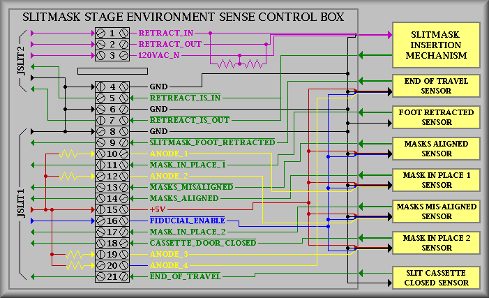
Sheet 7 gives the wiring details of the terminal located in the Slitmask Stage Environment Sense box. The lines have been color coded to help identify the various signals. The magenta lines represent 120 VAC wiring, the black represents signal gnd, green represents input signals to the Galil, yellow represents the pull-ups for the sensors, red represents +5 VDC, and blue represents the enable signal for the sensors. Again, note that the 'Foot Retracted' and 'Slit Cassette (Door) Closed' sensors are actual limit switches and don't need to be enabled.
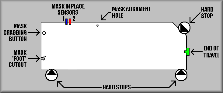
Simplified drawing
Above is a view of a slitmask inserted into the Slitmask Form. The hard stops define the correct positioning of the slitmask while the various sensors are read by the software to confirm complete insertion of the mask. The truth table
Simplified drawing
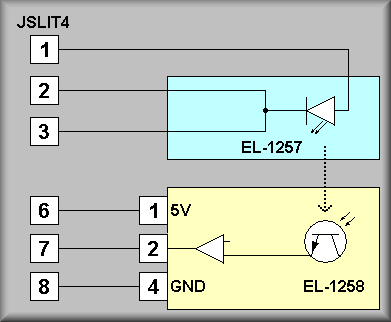
Above is a simplified version of the IRLED/Phototransistor sensor that is used to determine that all of the slitmasks are properly retracted. This doesn't cover the case where slitmasks have been moved inward of the sensor.