Barrel Stage Wiring
The barrel stage wiring section of this manual contains descriptions of the individual stage wiring for the barrel portion of the DEIMOS Spectrograph. It corresponds to the Barrel Stage Wiring tab in the electronics schematics binder.
Science Filterwheel Stage, ![]() EL-3056
EL-3056
Schematic: schematics/FILWHEEL.sch.pdf
Page last updated: July 1, 2002
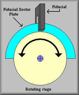
Simplified Drawing
Along with the TV Filterwheel, the Science Filterwheel is an unconstrained, rotational stage. Electronically, these stages consist of a DC servo motor with integral optical disc encoder and a digital vane switch. The motor/encoder is from Galil and is the same basic motor that has been used both in the ESI and HIRES instruments. The Galil part number is 50-1000. The motor is rated at 30 oz-in (0.21 Nm) of torque, 3750 rpm, and 1000 line encoder. The encoder supplies A and B phases in quadrature and thus is decoded to 4000 counts per revolution. A Cherry Corp. Digital Vane Switch, VN101501, is used for the stage fiducial. (This is the only stage in the instrument to use this type switch.)
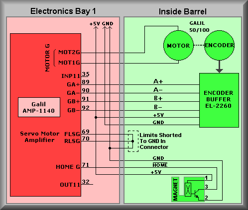
The Science Fliterwheel is connected to channel G of the controller via the Galil AMP-1140 module. The connections shown on the amplifier module refer to the screw terminals thereon. For instance, the encoder output connections are made to screw terminals 89-92. The signal names on the amplifier module reflect the A+ and A-, and the B+ and B- phases of the encoder. The second letter, A, refers to the controller channel to which the signals are connected. At the bottom of the diagram are the connections to the HOME fiducial. The signal OUT11 is not used on this stage because of the use of a magnetic fiducial. By executing a homing routine, the stage can set to a known zero point and subsequently to any of the filters positions which are a fixed distance from the HOME point. As indicated on the drawing, Ground and +5 volts are supplied to both the encoder and the fiducial switch.
Because this stage is unconstrained, the connections made to the FLSG ( Forward Limit Switch channel G) and the RLSG ( Reverse Limit Switch channel G) are tied to ground. Also, there is no connection to the INP11 input. This input on other constrained or linear stages is used to read the state of the Secondary Limits.
The stage is operated by running the HOME sequence and then selecting one of the ordinal filter positions. From the user's standpoint, the homing routine is transparent, meaning that if the system needs to be homed the low level software takes care of it without the user being aware that it is happening. On the otherhand, the technician needs to know that without performing the homing sequence the filter positions won't correspond to the light path.
The science filterwheel is connected to channel G of controller #1 via the Galil AMP-1140 module. The connections shown on the amplifier module refer to the screw terminals thereon. For instance, the encoder output connections are made to screw terminals 77-80. The signal names on the amplifier module reflect the A+ and A-, and the B+ and B- phases of the encoder. The second letter, A, refers to the controller channel to which the signals are connected. At the right-hand side of the drawing is the EL-2260 Encoder Buffer board. This board converts the unipolar encoder outputs to differential signals and drives the encoder cable. At the bottom of the amplifier block are the connections to the HOME fiducial. The signal OUT11 is used to enable the slotted optical switch, or the fiducial. A clear bit instruction, CB11, pulls the output line low causing the emitter section of the fiducial to turn on which illuminates the receiver portion of the switch. With this done, the stage can be moved to find the edge of a blade that is attached to the stage.
Stage Homing
This stage has none of the normal limit switches only the home fiducial.
Troubleshooting:
2. Cables: The first thing to look at is the cabling. Start at Galil controller panel #1 and check that it's stage cable is connected to J7. (As this stage does not use an auxiliary encoder, there should be no cable connected to J27). Next, look at the EL-1236 interconnect box cables. It is located inside the instrument near the man hatch and labeled Science Filterwheel. The main cable comes into the box from the rear part of the instrument and connects to JB1. The connectors leaving the box on the other side are JB2, JB3, and JB6. JB2 is the motor power cable. JB3 contains the connections for the primary limits and the fiducial. Notice on the stage drawing that the primary limit switch signals are wired to GND. If the connector were unplugged you would get a primary limit error because with the cable off the controller sees the forward and reverse primary limits as being made (i.e. the input floats high.) The last cable is the ribbon cable that connect the motor encoder to the controller. If this cable was off the controller would try to move the stage. The motor would start to turn but the encoder would not change. Because the software sets the OE (Off on Error) the motor will turn off as soon as it has moved a small way. This is the result of the error in commanded position versus actual position has grown larger then the ER error value.
3. Power Supplies: The next logical place to check is the power supplies.
The supplies in question are the 28V motor power, the 5V, +/-12V logic power,
and finally the power supplies in the Galil controller. First, open the necessary
covers on the electronics ring to gain access to Galil panel #1. The Logic Supply
+5V can be measured across the +5 and GND terminal strips TBA and TBB. The +28V
power supply can be measured across the two large large terminals on the Lambda
power supply. The trickiest to measure is the Logic Supply +/-12V supplies.
To get to the terminals of this supply the supply has to be removed from the
Galil panel. To do this, remove the AC power cord that supplies the panel (the
second power cord on the Panel plugs directly into the Galil controller and
needn't be unplugged). Next, locate and remove the clear plastic AC shield that
protects the AC input terminals of the logic supply. Remove the Allen head cap
screws that attach the Logic Supply to the Opto-22 relay rack support. Now lay
the supply out to where you can get to the +/-12V terminals with a meter and
carefully plug the AC power back in. Measure between the +12V terminal and any
GND terminal on TBB. Do the same for the -12V supply. On the Galil, extra connectors
have been crimped onto the ribbon cables that connect the controller to the
amplifiers. These connectors provide test points for all of the signals from
the controller, including the internal power supply lines. To measure the Galil
power supply insert probes into the following pins
Ground Pin 1 +5 volts Pin 59 +12 volts Pin 57 -12 volts Pin 58
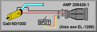
4. Isolate the problem: Use a spare Galil 50/1000 motor to determine if the motor is being servoed. This can be done by connecting a spare motor by using the motor/limit test setup as shown below to the stage interconnect box.
Motor Test Connector
Step 1: Stop dispatcher #1 and login to Galil controller #1:
- log onto keamano as kics using the kics password for keamano.
- Type: deimos stop dispatcher2.1
- telnet to Galil #1: telnet 192.168.1.2 2005
- Hit <return> a couple of times until you get the colon prompt :
Step 2: First, issue a MO (Motor Off) from the Galil command line. This will remove power from all motors if it is not already off. Disconnect the motor connector JB2 and the encoder connector JB6 from the stage interconnect box. Connect the Motor Test Connector's JB2 motor connector and JB6 encoder ribbon cable connectors. Now issue a SHG (Servo Here channel G) from the Galil command line. This should servo the motor and you should feel stiff resistance to rotating the shaft. If the motor runs away, remove motor power as above with the MO command, swap the red and black wires at the motor, and servo the motor again. Swapping the motor leads should ensure the motor runs the same direction as the encoder. If the motor runs away again the problem is likely that either 1) the EL-2260 Encoder Buffer has failed, 2) there is a problem in the Interconnect Box, or 3) there is a problem in the stage cable. If this is the case, next try inserting the spare EL-1236 Interconnect Box in place of the original and repeat the above test. If this test fails inspect the cable ends and pins for broken or bent pins. If the test motor servos but the stage motor doesn't, carefully check the wiring from the interconnect box to the motor. If the wiring looks OK, issue the MO command and reconnect the stage cables JB2 and JB6 to the interconnect box. Disconnect the red and black leads from the motor and connect them to the test motor. Issue the SHG command and again test the motor shaft for servo power.
Step 3: (This step omitted for rotory stages.)
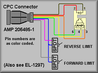
Step 4: If the above steps tell you that the motor and it's wiring are OK then install the Limit Test connector to test the primary limits and the fiducial input. First, set both test switches into the closed positions. Next, issue the command TSG (Tell Switches G axis). This will tell you the state of the primary limits.
Limit Test Connector
Convert the hex number that is returned into binary to check the states of the various limit inputs. Bit 3 will tell you the state of the forward limit switch and bit 2 will tell you the state of the reverse limit switch. Now, change the forward limit test switch and issue the TSG command again. You should see that the value read back has changes by 4. Repeat the test for the reverse switch and see that the returned value now changes by 2.
Step 5: Test the fiducial. First, enter the command: SB11. Now, issue the command TSG. Convert the hex number that is returned into binary to check the state of the HOME input. Bit position 2 should read as a 1. If not, look for short to ground on the HOME signal wire. If it does read as a 1 then issue the command CB11. This turns on the emitter section of the optical slotted switch. With the slot not blocked, issue the TSG command again. This time bit position 2 should read as a 0. If not, look for a short to ground on the HOME signal wiring. Now, block the slotted switch and issue the TSG command again. Bit position 2 should read as a 1 once again.
Step 6: If the stage is still not functioning correctly try isolating the main stage cable by plugging the stage test cable into J7 of Galil controller #1. Plug the other end into the spare EL-1236 Interconnection box. Plug in both the Motor Test connector and the Limit Test connectors into the interconnection box and start back at step 2 above.
Step 7: After replacing any defective components restart the above procedure at step 2.
Step 8: Logout and restart the dispatcher:
To exit:<Control> ] (control key and right bracket key)
telnet> quitRestart Dispatcher:deimos start dispatcher2.1