Barrel Electronics
The barrel electronics section of this manual contains descriptions
of the barrel electronics for the DEIMOS Spectrograph. It corresponds to the
Barrel Electronics tab in the electronics schematics binder.
Analog
Environment Monitoring Controller #1,  EL-3015
Schematic: schematics/ANALIN1.sch.pdf, ANALIN2.sch.pdf
Page last updated: June 14, 2002
For troubleshooting, note that
the Galil's software toggles the address lines continuously. To get around
this difficulty see test fixture at bottom of
this page.
The simplified schematic shows that only 3 non-dedicated channels
are used on controller #1. They are the electronics ring enclosure sensor mounted
near the CCD controller power supply box, the electronics ring enclosure sensor
mounted near the Galil controllers, and the coolant temperature sensor mounted
at the coolant flow meter that lives at the front of the instrument.
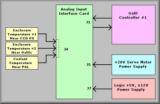
Analog input card on controller #1
The analog input boards are used for two purposes. First, they multiplex up
to 24 inputs into 3 analog levels that are fed to Galil analog inputs 1-3. And
secondly, it provides monitoring of the system power supplies. Five of the available
inputs are dedicated to monitoring power supplies. These are inputs 1C, 2C,
3C, 4C, and 7C. They are dedicated to the following inputs:
|
INPUT
|
|
FUNCTION
|
|
1C
|
|
5V supply
|
|
2C
|
|
+/- 12V supplies
|
|
3C
|
|
Servo supply 1 (28V)
|
|
4C
|
|
Servo supply (not used)
|
|
7C
|
|
Onboard temperature sensor
|
Input 5C, 6C, and 8C are available to be wired into J4 of the board. As noted
in the table above, the second servo supply at input 4C (input connector J6)
is not used on the DEIMOS instrument. It is provided to make the board compatible
with other systems. The simplified drawings show what inputs enter the board
on what connectors.
The use of three multiplexed channels can be confusing to explain, but the
following drawing should make it clearer:
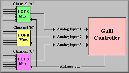
Click here to go to the detailed
description of the analog interface card.
Analog
Environment Monitoring Controller #2,
The simplified schematic shows that none of the non-dedicated channels are
used on controller #2. The only monitored inputs are the power supply inputs.
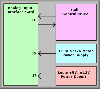
Analog input card on controller #2
The analog input boards are used for two purposes. First, they multiplex up
to 24 inputs into 3 analog levels that are fed to Galil analog inputs 1-3. And
secondly, it provides monitoring of the system power supplies. Five of the available
inputs are dedicated to monitoring power supplies. These are inputs 1C, 2C,
3C, 4C, and 7C. They are dedicated to the following inputs:
|
INPUT
|
|
FUNCTION
|
|
1C
|
|
5V supply
|
|
2C
|
|
+/- 12V supplies
|
|
3C
|
|
Servo supply 1 (28V)
|
|
4C
|
|
Servo supply (not used)
|
|
7C
|
|
Onboard temperature sensor
|
Input 5C, 6C, and 8C are available to be wired into J4 of the board. As noted
in the table above, the second servo supply at input 4C (input connector J6)
is not used on the DEIMOS instrument. It is provided to make the board compatible
with other systems. The simplified drawings show what inputs enter the board
on what connectors.
The use of three multiplexed channels can be confusing to explain, but the
following drawing should make it clearer:
Click here to go to the detailed
description of the analog interface card.
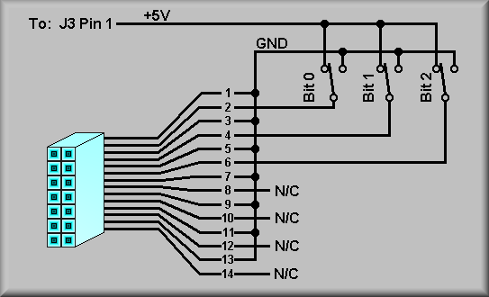
Troubleshooting:
The software running on the Galil controller makes it almost impossible to
look at the individual analog inputs. To aid in troubleshooting the system,
a test connector EL-1298, has been shipped with the instrument. It connects
to the 14-pin IDC connector on the analog card and allows you to manually select
which of eight inputs to monitor. With the connector in place simply set the
desired output with the switches and read the output of the multiplexers or
the value of the analog inputs.