TV
AC Power Interrupt Box, ![]() EL-3013
EL-3013
Barrel Electronics
The barrel electronics section of this manual contains descriptions of the barrel electronics for the DEIMOS Spectrograph. It corresponds to the Barrel Electronics tab in the electronics schematics binder.
TV
AC Power Interrupt Box, ![]() EL-3013
EL-3013
Schematic: schematics/TVINTERRUPT.SCH.pdf
Page last updated: June 14, 2002
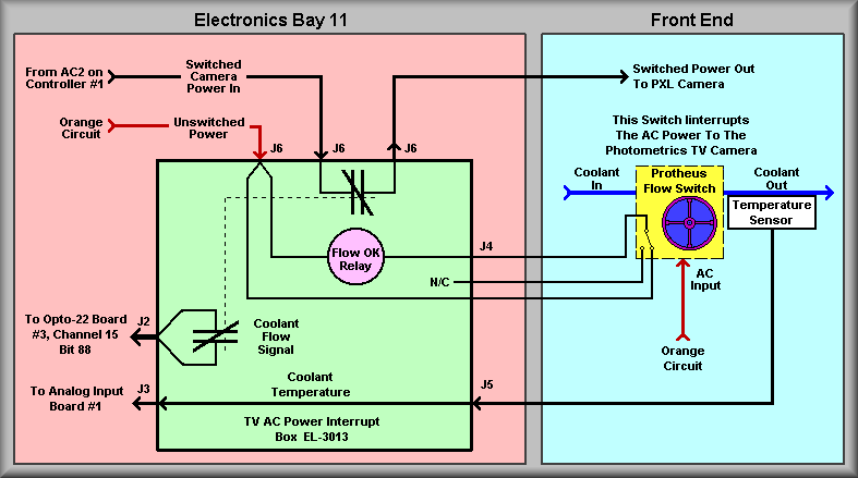
Simplified Drawing
The above drawing show the workings of the TV AC power interrupt box. The function of the box is to interrupt the AC power to the Photometrics PXL TV Camera Controller if the instrument loses coolant flow. The camera is not meant to be used without cooling. The box contains a mechanical relay and connectors for the wiring of the system. The drawing shows that the contacts used are the 'normally closed' contacts that allow the AC to flow to the camera and the associated I/O input bit. The yellow block represents the Protheus flow switch. The flow switch is adjusted to turn off when the coolant flow rate drops below 0.2 GPM. The normal flow rate is 0.4 GPM. A solid-state LM35 temperature sensor is mounted to the copper pipe that connects to the flow switch. For ease of wiring, the sensor was cabled through the interrupt box. Also entering the interrupt box are normal orange 'clean' AC power that powers the relay, and the switched power from the Opto-22 relay that turns on the TV Camera Controller. To complete the wiring, an orange duplex outlet was added to the front area of the instrument to plug the flow switch into.
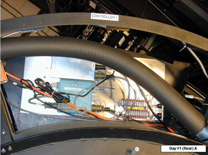
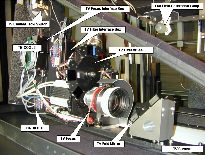
Photos: