Photometrics
TV Power Control, ![]() EL-3012
EL-3012
Barrel Electronics
The barrel electronics section of this manual contains descriptions of the barrel electronics for the DEIMOS Spectrograph. It corresponds to the Barrel Electronics tab in the electronics schematics binder.
Photometrics
TV Power Control, ![]() EL-3012
EL-3012
Schematic: schematics/TVPWR.sch.pdf
Page last updated: June 14, 2002
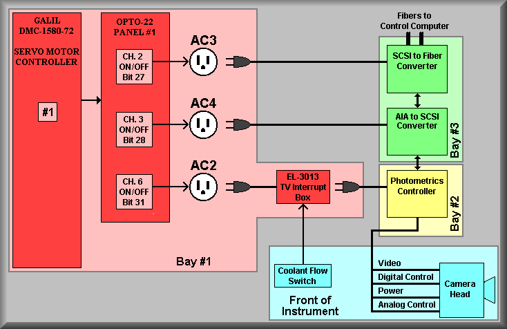
Simplified Drawing
This drawing shows the power control wiring for the Photometrics PXL TV camera system. The PXL camera controller is picky about it is powered up. To allow for this, we have give software the ability to bring up the entire system. First, the SCSI to Fiber controller is turned on, then the AIA to SCSI controller and finally, the Photometrics controller. As is shown above, the TV controller has another control for it's power. The camera is not meant to be used without coolant flow so a coolant flow switch is used to ensure that if the coolant is not flowing the camera can't come on. The pink block shows the equipment that is located in Bay 1 of the DEIMOS electronics ring and includes the Galil controller 1, Opto-22 panel 1, AC outlets AC2, AC3, and AC4 and the TV interrupt box. The AC outlets for the TV controller and interface boxes are shown with their associated I/O bits and relay channels. The green panel indicates that the SCSI to Fiber and AIA to SCSI boxes are mounted in Bay 3 and the blue panel indicates that the PXL camera controller and the Protheus flow switch are mounted at the front of the instrument. Please refer to the actual schematic for detailed wiring.
Photos:
 |
 |
 |
|
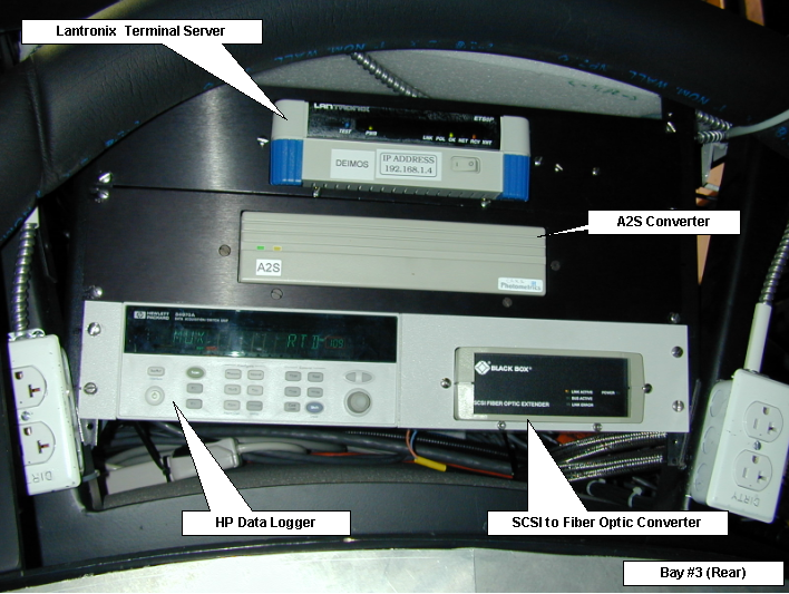
SCSI-to-Fiber & |
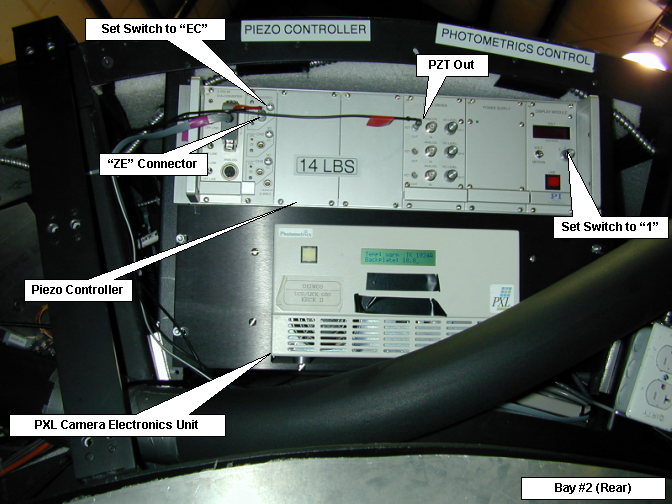
Photometrics TV |
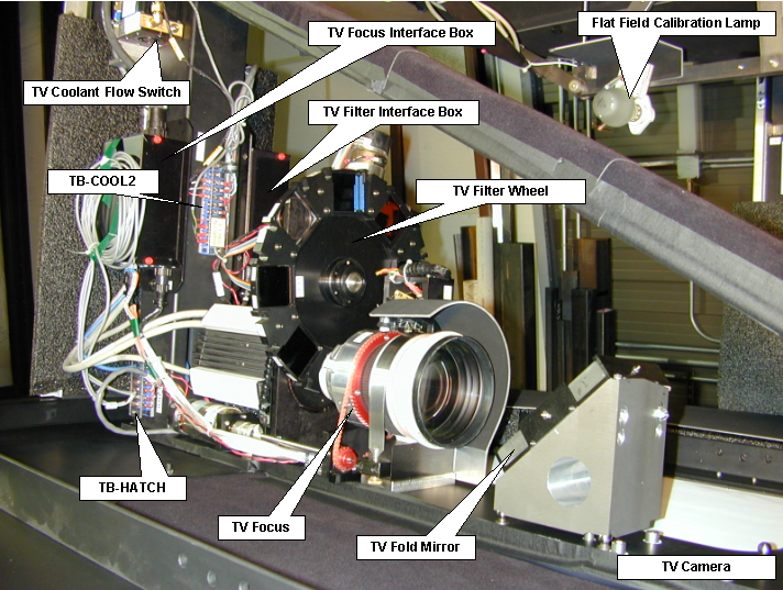
Camera Head &
Flow Switch |