APF Spectrograph Electronics
APF over-temperature shutdown box,  EL-3697
 |
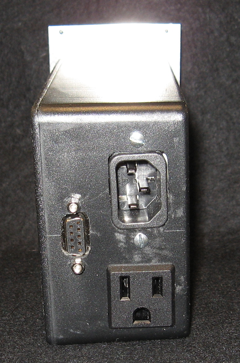 |
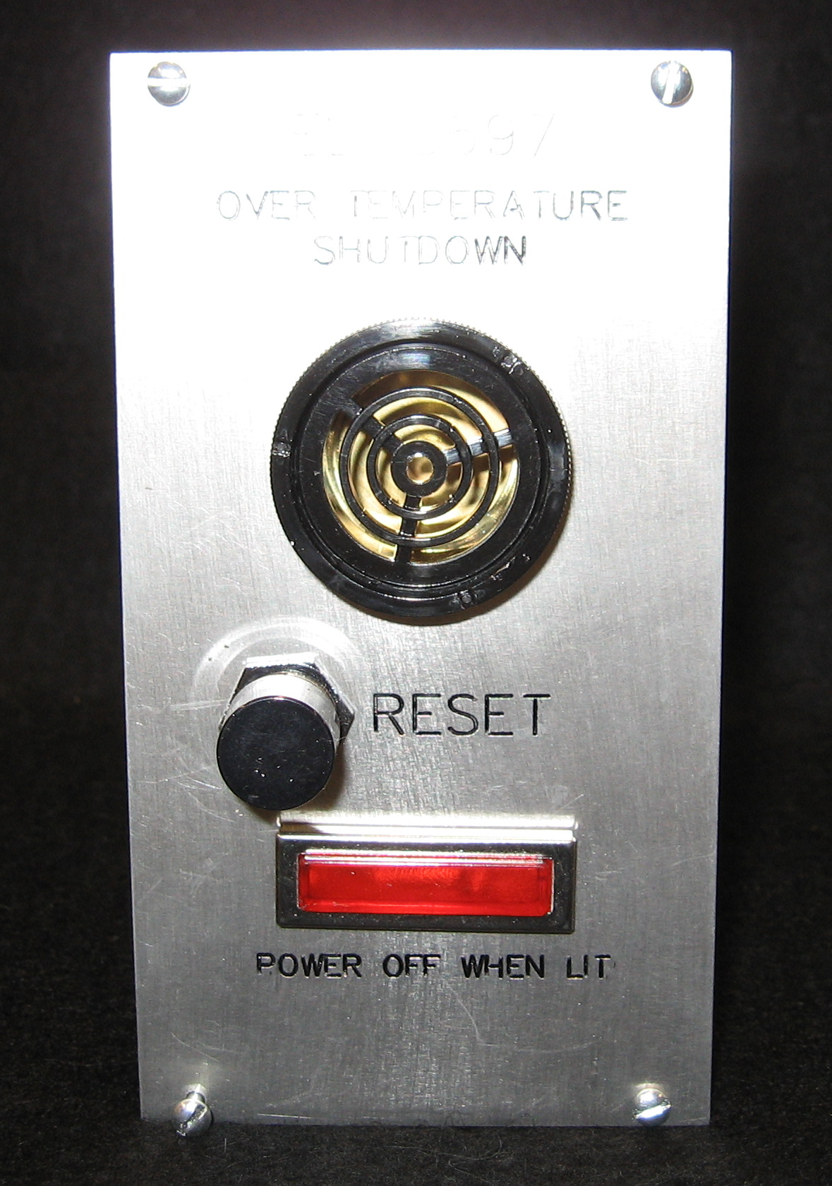
| Front View | Rear view |
The EL-3597 Over-temperature shutdown box is a standard UCO/Lick Electronics Lab power controller packaged to be installed in a plastic box attached to a 3U front panel. The circuitry was first developed for the HIRES instrument by Terry Ricketts. In this case, it was desired to have individual boxes for the calibration lamps, iodine cell, and CCD controller. Thus, the large contactor-style relay was replaced with a smaller relay because each circuit draws much lower current. All three boxes, plus a spare, are wired exactly the same.
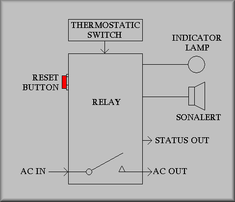
Simplified Drawing
The above, simplified drawing shows the functionality of the box. The box receives AC power from a standard plug. The Line side of the power is run through one of the four relay contacts. As long as the thermostatic switch contacts remain open the AC power flows through the relay. If, however, the temperature at the switch raises higher than 85 degrees F the contacts will close which will apply power to the relay coil which will disconnect the out AC output and turn on both the Sonalert and the over-temperature indicator lamp. The lamp is needed to indicate which circuit is tripped - the sonalerts are all the same and it can be hard to tell exactly which one is on. Once the circuit is tripped it can only be reset in two ways. For either way, the thermostatic switch must cool down and open its contacts or the alarm will trip right away. Once the switch does open again the circuit can be reset either by manually pressing the red reset button on the box's front panel or by cycling the power coming into the box - this can be done remotely via software by cycling the Pulizzi outlet for the tripped circuit. To do so,
Detailed circuit description: (Adapted from Terry Ricketts original write-up)
Because the instrument is operated remotely, any failure in the cooling system could cause the temperature of various components/subsystems quickly rise to levels that could damage the components. This circuit is designed to prevent such a failure from destroying those electronic components.
The main power for the component is applied to input connector (left side of the drawing). The ground and neutral lines are sent directly to the output connector. The hot line is routed through one contact of the relay pins 1 and 6. From relay pin 9 the power is sent to the output connector.
The hot line is also applied to one side of the relay's coil via the Reset switch. If the neutral line is applied to the other side of the coil the circuit will be completed and the relay will pull in and disconnect the hot line from the output connector. The other side of the coil can be connected to the neutral line by an electromechanical thermostat that is mounted to the protected component. The thermostat has a trip point of 85 degrees F. If the temperature exceeds the trip point the contacts of the thermostat will close and apply the neutral to the coil of the relay.
If the relay's coil is energized it will open the contact (the top contact of the relay) that supplied power to the output power connector. Via pin-10 of the relay, it will also apply power to the box mounted sonalert and neon pilot lamp to alert any local user that the power has been disconnected. The bottom contact in the drawing will latch the relay on so that power will be prevented from being reapplied until the manual reset button is pressed.
Mounted on each of the EL-3597 boxes is a red button labeled 'RESET'. If this button is pushed, power will be remove from the relay coil. This will restore power to the component. CAUTION: if one of these circuits is triggered there is a serious cooling problem. Power should not be restored until the problem is found and corrected.
Sheet 2, , APF_over-temp_sh_2.pdf
Sheet 2 shows a pictorial wiring list for the box. Please refer to the description above for the box functionality.