Hamilton Spectrograph
This section contains descriptions of the electronics version 2 of the Hamilton Spectrograph.
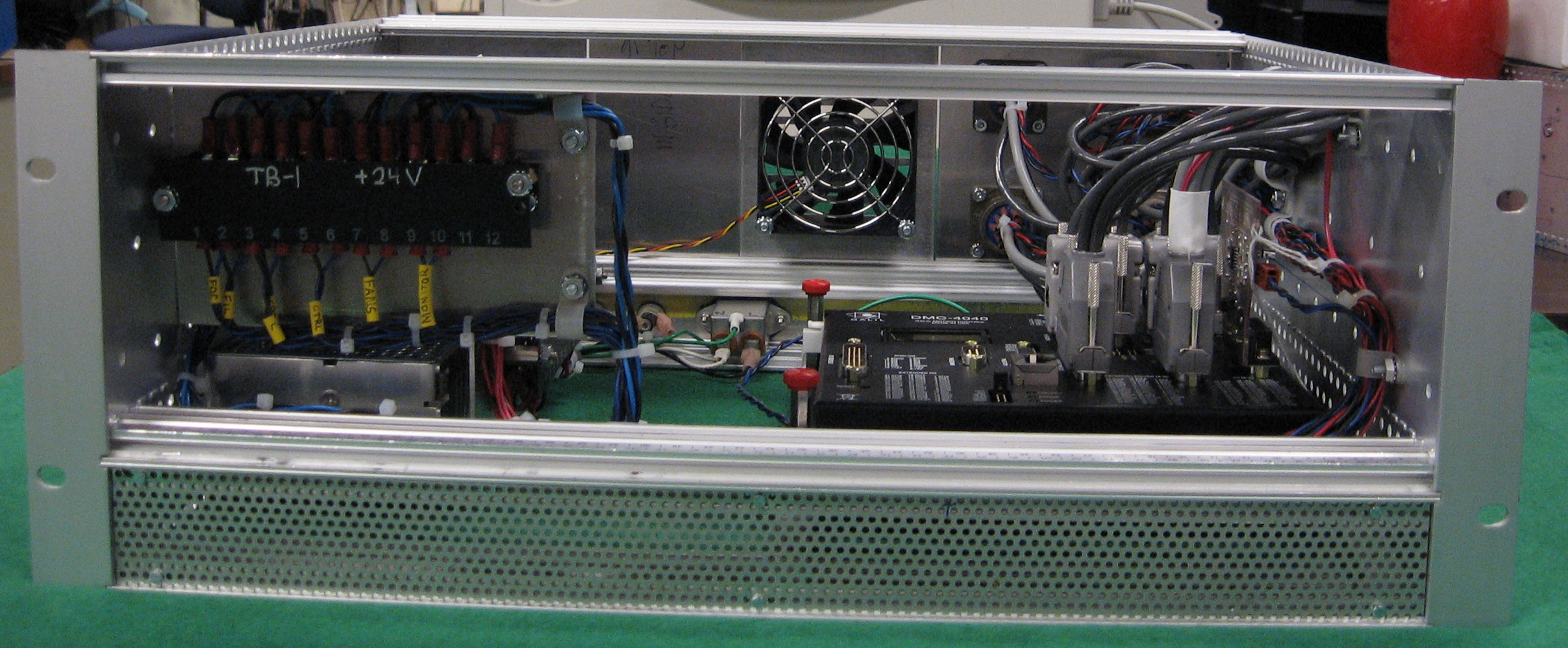
4-Channel Chassis Wiring, EL-4004 ![]()
Schematic: schematics/HAM_II_box_2_wiring_sh_1.pdf
Page last updated: June 30, 2010
 |
 |
 |
 |
|---|---|---|---|
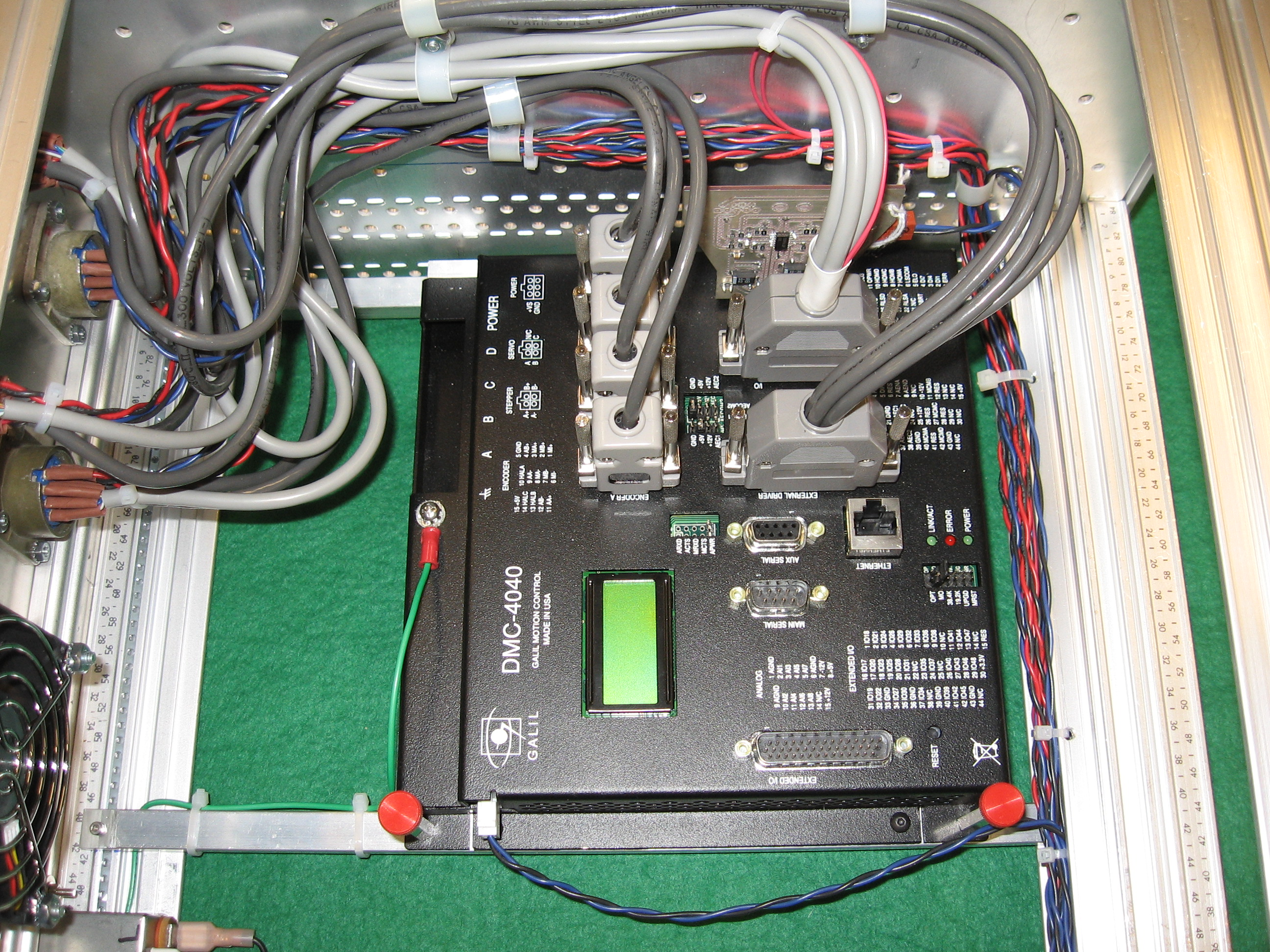
Front |
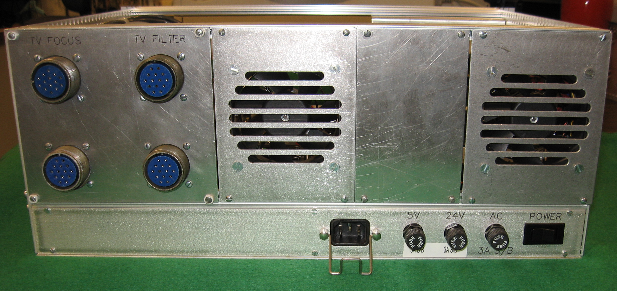
Rear |
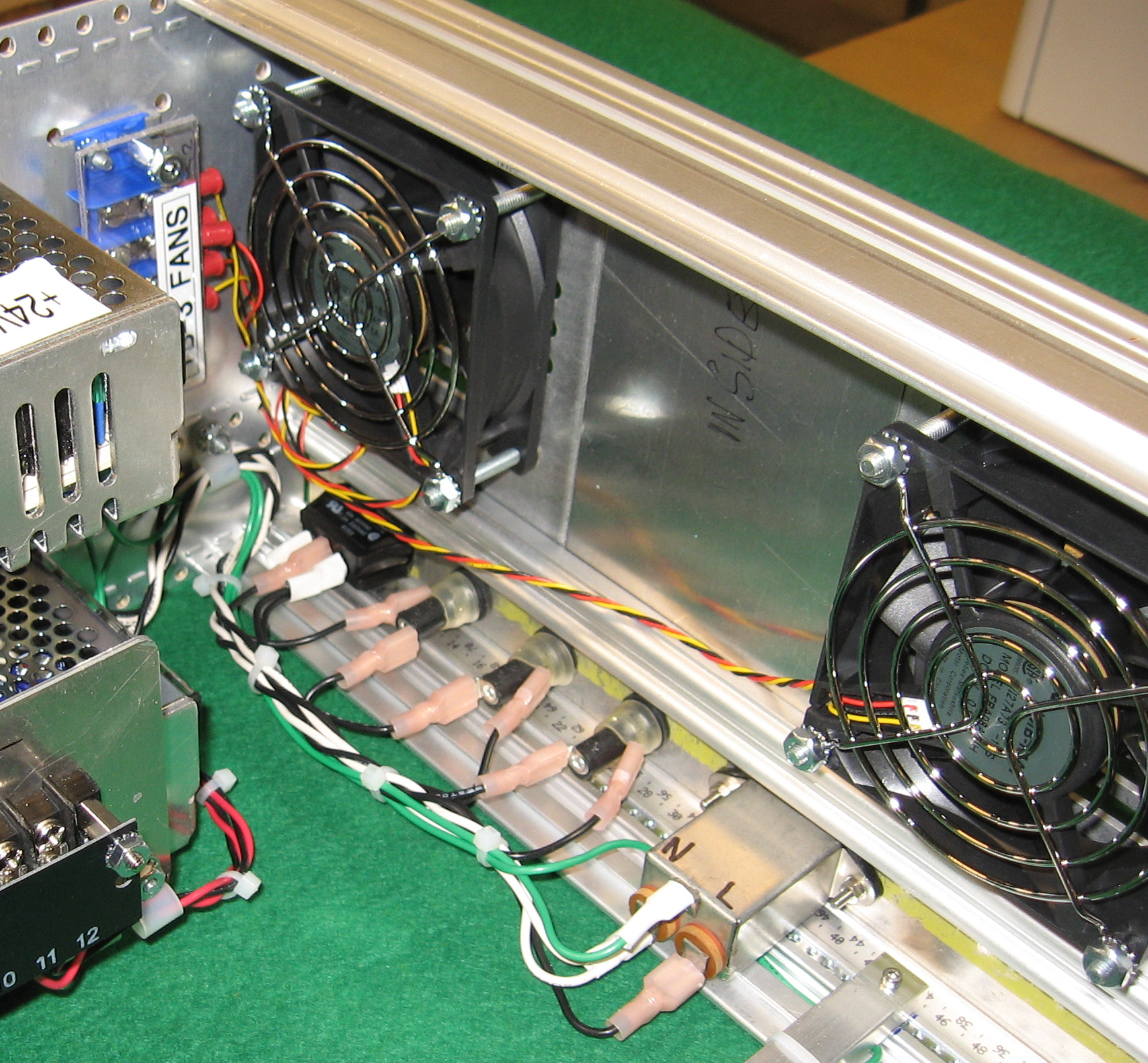
AC wiring |
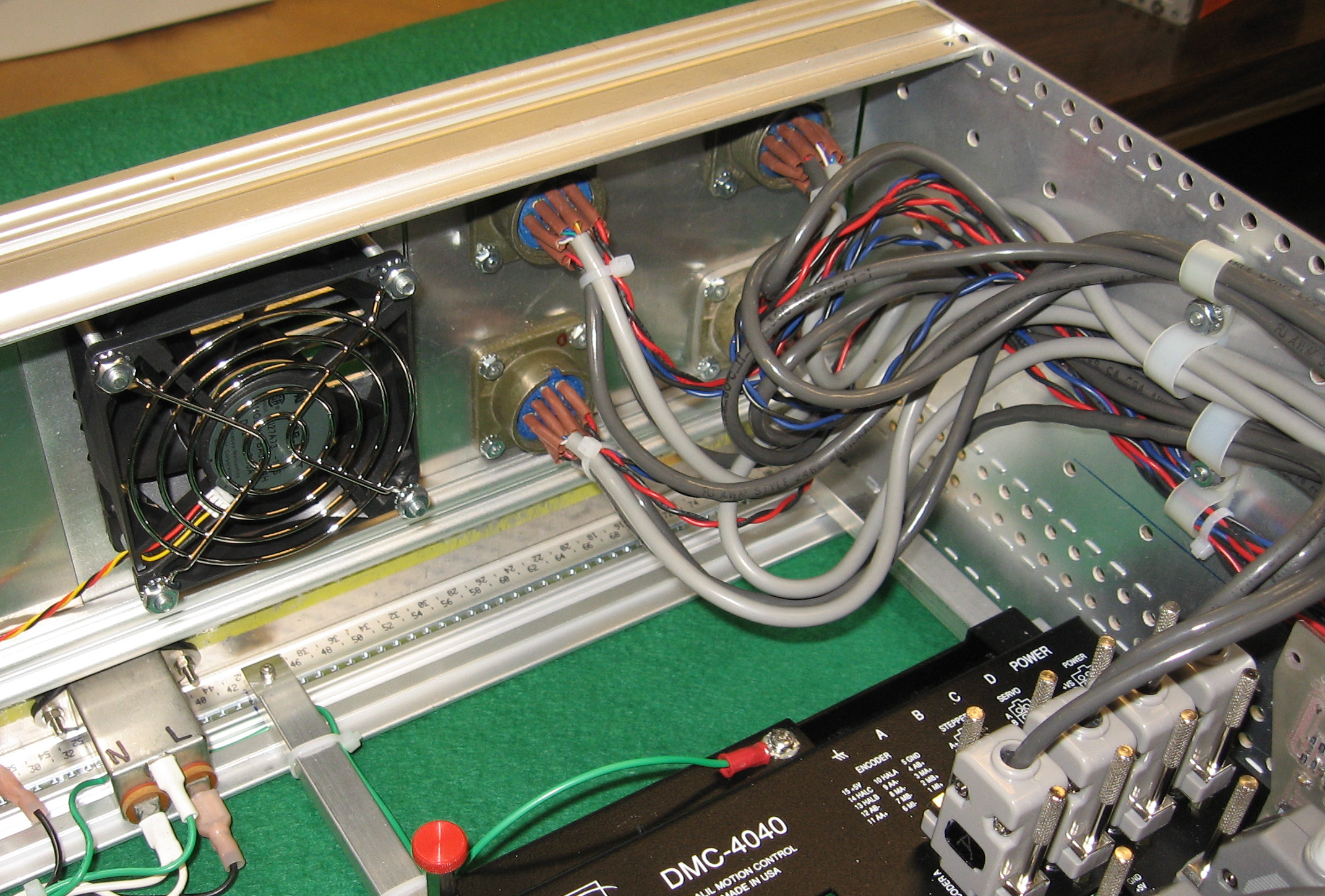
Stage wiring |
 |
 |
 |
|
Galil |
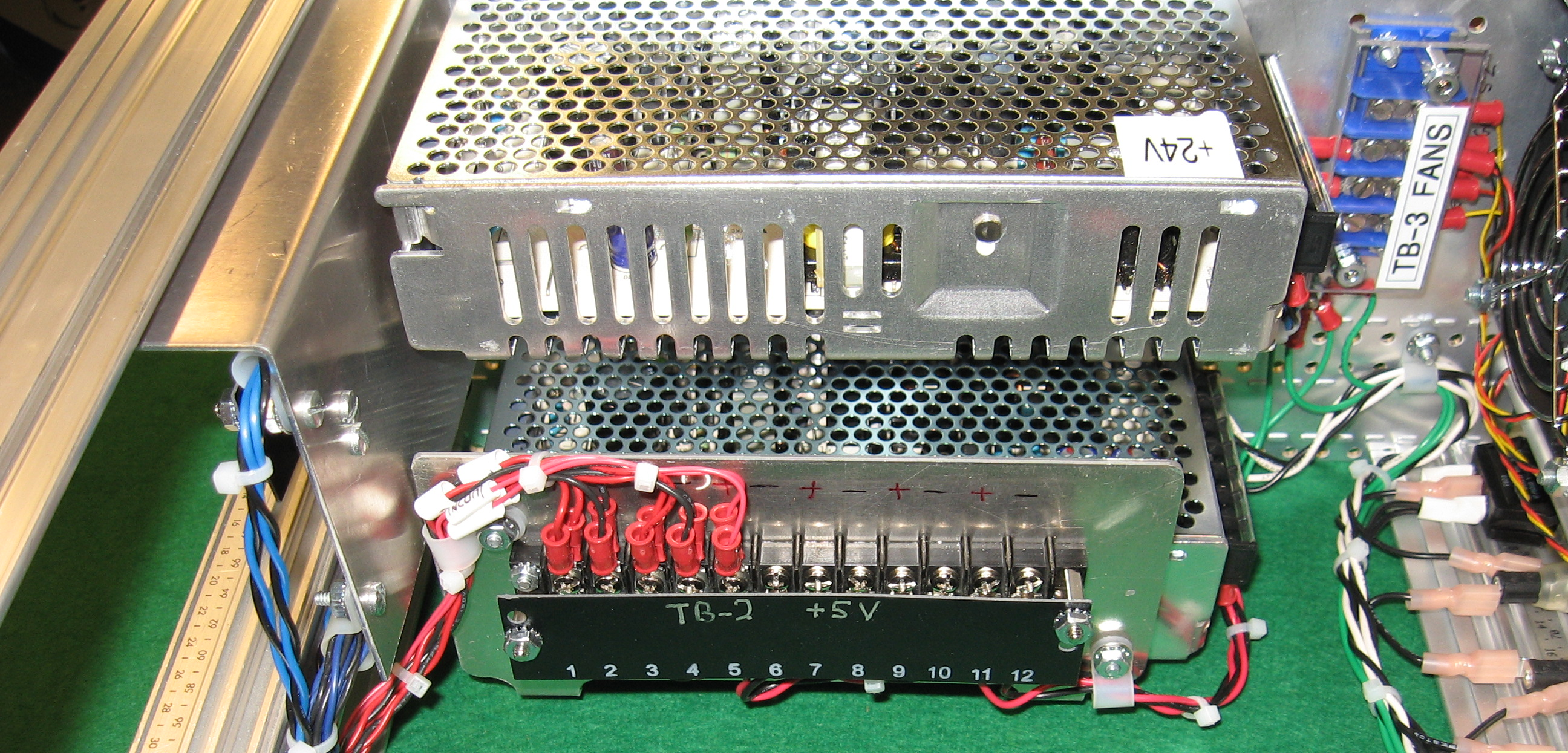
Power supplies and 5V terminal strip |
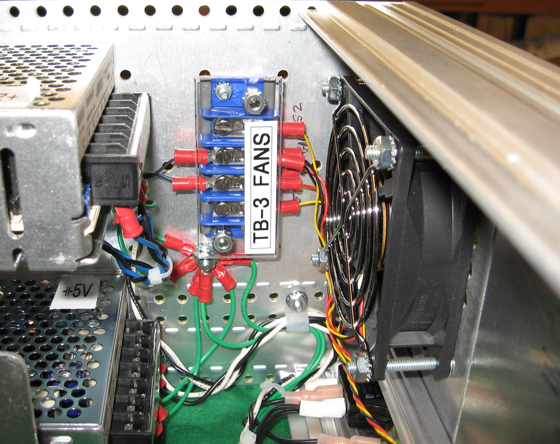
Fan terminal strip |
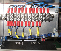
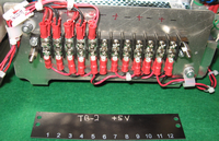
The above photos show various views of the 4-channel Hamilton Spectrograph controller chassis. These all were taken before top and bottom covers were added and are meant to show interior components, wiring, and terminal strips
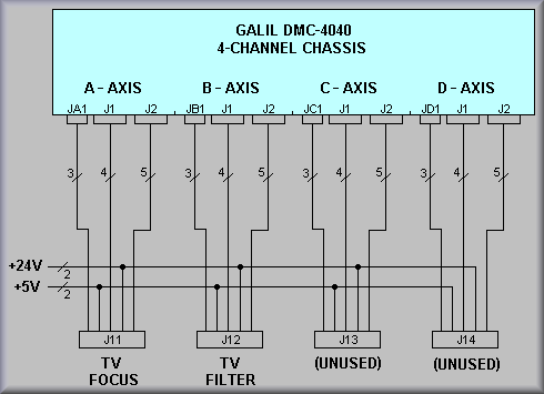
Fig. 1 Simplified Diagram
Figure 1 above shows that the main interconnect wiring in the controller consists of power supply wiring, encoder wiring from Jx1, external driver signals from J1, and general I/O from J2. Note that each axis has an encoder connector but that all axes share J1 and all share J2.
The only wiring to the encoder connectors are pins 1 - INDEX+, 5 - GND, and 15 - +5V. Currently, only the Grating Tilt, and Slit stages have the INDEX+ signals wired at the stage. In these two cases there is a slotted disk attached to the motor shaft. In the earlier version of the electronics, a optical slotted vane switch was used which required the software to turn on the emitter side of the switch and then look for the appropriate change of input level to zero the stage. In the newer controller the Hall-effect switches remove the necessity of turning on the emitter. The software will now perform a homing operation to get the "rough" position and then perform a slow speed find index operation to achieve the same one-step positioning as the original system.
The signals from J1 include the Motor Enable, Step, and Direction signals for each axis. These signals run to pins E, F, and G respectively. These signals are wired to the corresponding inputs of the Applied Motion ST5-S drivers located in each stage's EL-4006 driver box.
The signals wired to J2, the general I/O connector, include HOME, FWD_LIM, REV_LIM, and ERROR. The home and limits signals are wired through the driver box and out to the respective sensors. The ERROR signal originates on the Applied Motion driver and comes back to to digital inputs 1, 2, 3, or 4 depending on the axis. The ST5-S asserts the ERROR signal when it detects a problem. If the signal is asserted, the technician should check the status LEDs to determine the problem. Please refer to the EL-4006 write-up to troubleshoot driver problems.
schematics/HAM_II_box_2_wiring_sh_2.pdf
GALIL |
TO |
Function |
GALIL |
TO |
Function |
|
|---|---|---|---|---|---|---|
| 1 Reserved | 23 Amp enable C | J13 - E |
DEWAR FOCUS | |||
| 2 PWM C/Step C | J13 - F |
DEWAR FOCUS | 24 NC | |||
| 3 Reserved | 25 +12V Out | |||||
| 4 Reserved | 26 Reserved | |||||
| 5 Sign C/Dir C | J13 - G |
DEWAR FOCUS | 27 Motor command C | |||
| 6 Reserved | 28 Reserved | |||||
| 7 Amp enable A | J11 - E |
GRATING TILT | 29 NC | |||
| 8 Amp enable D | J14 - E |
SLIT STAGE | 30 NC | |||
| 9 NC | 31 PWM B/Step B | J12 - F |
DEWAR HEIGHT | |||
| 10 -12V Out | 32 Reserved | |||||
| 11 Motor command B | 33 Ground | |||||
| 12 Reserved | 34 Sign B/ Dir B | J12 - G |
DEWAR HEIGHT | |||
| 13 NC | 35 Reserved | |||||
| 14 NC | 36 Ground | |||||
| 15 +5V Out | 37 Amp enable B | J12 - E |
DEWAR HEIGHT | |||
| 16 PWM A/Step A | J11 - F |
GRATING TILT | 38 Amp enable common 2 | |||
| 17 Reserved | 39 Ground | |||||
| 18 PWM D/Step D | J14 - F |
SLIT STAGE | 40 Motor command A | |||
| 19 Sign A/Dir A | J11 - G |
GRATING TILT | 41 Reserved | |||
| 20 Reserved | 42 Motor command D | |||||
| 21 Sign D/Dir D | J14 - G |
SLIT STAGE | 43 Ground | |||
| 22 Amp enable common 1 | 44 NC |
schematics/HAM_II_box_2_wiring_sh_3.pdf
GALIL |
TO |
Function |
GALIL |
TO |
Function |
|
|---|---|---|---|---|---|---|
| 1 Error output | 23 Reverse limit B - isolated | J12 - I |
DEWAR HEIGHT | |||
| 2 Input 1 - isolated | J11 - N |
GRATING ERROR SIGNAL | 24 Reverse limit C - isolated | J13 - I |
DEWAR FOCUS | |
| 3 Input 4 - isolated | J14 - N |
SLIT ERROR SIGNAL | 25 Reverse limit D - isolated | J14 - I |
SLIT STAGE | |
| 4 Input 7 - isolated | 26 NC | |||||
| 5 Elect Lockout - Input - iso. | 27 Output 2 - isolated | |||||
| 6 Limit switch common - LSCOM | 28 Output 5 - isolated | |||||
| 7 Home A - isolated | J11 - J |
GRATING TILT | 29 Output 8 - isolated | |||
| 8 Home B - isolated | J12 - J |
DEWAR HEIGHT | 30 +5V out | |||
| 9 Home C - isolated | J13 - J |
DEWAR FOCUS | 31 Ground | |||
| 10 Home D - isolated | J14 - J |
SLIT STAGE | 32 Input 2 - isolated | J12 - N | DEWAR HEI. ERROR SIGNAL | |
| 11 Output power+ | 33 Input 5 - isolated | |||||
| 12 Output 3 - isolated | 34 Input 8 - isolated | |||||
| 13 Output 6 - isolated | 35 Ground | |||||
| 14 Output return | 36 Forward limit A - isolated | J11 - H |
GRATING TILT | |||
| 15 +5V Out | 37 Forward limit B - isolated | J12 - H |
DEWAR HEIGHT | |||
| 16 Reset - isolated | 38 Forward limit C - isolated | J13 - H |
DEWAR FOCUS | |||
| 17 Input common - INCOM | 39 Forward limit D - isolated | J14 -H |
SLIT STAGE | |||
| 18 Input 3 - isolated | J13 - N | DEWAR FOC ERROR SIGNAL | 40 Ground | |||
| 19 Input 6 - isolated | 41 Output 1 - isolated | |||||
| 20 Abort - isolated | 42 Output 4 - isolated | |||||
| 21 NC | 43 Output 7 - isolated | |||||
| 22 Reverse limit A - isolated | J11 - I |
GRATING TILT | 44 Output Compare A-D |
schematics/HAM_II_box_2_wiring_sh_4.pdf
schematics/HAM_II_box_2_wiring_sh_5.pdf
J2 |
TO |
SIGNAL |
J1 |
TO |
SIGNAL |
GALIL |
TO |
SIGNAL |
||
|---|---|---|---|---|---|---|---|---|---|---|
2 |
FOC-l (A) |
ERROR |
2 |
SP2-F (C) |
STEP |
JA1 - 1 |
FOC-K (A) |
INDEX |
||
3 |
SP3-L (D) |
ERROR |
5 |
SP2-G (C) |
DIRECTION |
JA1 - 5 |
FOC-D (A) |
GND |
||
6 |
TB2-5 |
LSCOM |
7 |
FOC-E (A) |
ENABLE |
JA1 - 15 |
FOC-C (A) |
+5V |
||
7 |
FOC-J (A) |
HOME |
8 |
SP3-E (D) |
ENABLE |
|||||
8 |
FIL-J (B) |
HOME |
16 |
FOC-F (A) |
STEP |
JB1 - 1 |
FIL-K (B) |
INDEX |
||
9 |
SP2-J (C) |
HOME |
18 |
SP3-F (D) |
STEP |
JB1 - 5 |
FIL-D (B) |
GND |
||
10 |
SP3-J (D) |
HOME |
19 |
FOC-G (A) |
DIRECTION |
JB1 - 15 |
FIL-C B) |
+5V |
||
17 |
TB2-5 |
INCOM |
21 |
SP3-G (D) |
DIRECTION |
|||||
18 |
SP2-L (C) |
ERROR |
23 |
SP2-E (C) |
ENABLE |
JC1 - 1 |
SP2-K (C) |
INDEX |
||
22 |
FOC-I (A) |
REV_LIM |
31 |
FIL-F (B) |
STEP |
JC1 - 5 |
SP2-D (C) |
GND |
||
23 |
FIL-I (B) |
REV_LIM |
34 |
FIL-G (B) |
DIRECTION |
JC1 - 15 |
SP2-C (C) |
+5V |
||
24 |
SP2-I (C) |
REV_LIM |
37 |
FIL-E (B) |
ENABLE |
|||||
25 |
SP3-I (D) |
REV_LIM |
JD1 - 1 |
SP3-K (D) |
INDEX |
|||||
32 |
FIL-L (B) |
ERROR |
WIRE COLORS
|
JD1 - 5 |
SP3-D (D) |
GND |
||||
36 |
FOC-H (A) |
FWD_LIM |
MS PIN |
COLOR |
SIGNAL |
JD1 - 15 |
SP3-C (D) |
+5V |
||
37 |
FIL-H (B) |
FWD_LIM |
E |
BROWN |
ENABLE |
|||||
38 |
SP2-H (C) |
FWD_LIM |
F |
RED |
STEP |
WIRE COLORS
|
||||
39 |
SP3-H (D) |
FWD_LIM |
G |
BLACK |
DIRECTION |
MS PIN |
COLOR |
SIGNAL |
||
C |
RED |
+5V |
||||||||
|
WIRE COLORS
|
D |
BLACK |
GND |
|||||||
MS PIN |
COLOR |
SIGNAL |
K |
BROWN |
INDEX |
|||||
H |
VIO & WHT |
FWD_LIM |
||||||||
I |
GRN & BLU |
REV_LIM |
||||||||
J |
ORN & YEL |
HOME |
||||||||
N |
BRN & RED |
ERROR |
||||||||
Table 3.
SIGNALS |
TV F OCUS AXIS A | TV FILTER AXIS B | SPARE2 AXIS C | SPARE3 AXIS D | |||||||||
|---|---|---|---|---|---|---|---|---|---|---|---|---|---|
A |
ISO5V |
FOC-A |
TB2-1 |
FIL-A |
TB2-1 |
SP2-A |
TB2-3 |
SP3-A |
TB2-3 |
||||
B |
ISO_RTN |
B |
TB2-2 |
B |
TB2-2 |
B |
TB2-4 |
B |
TB2-4 |
||||
C |
ENCODER +5V |
C |
JA1-15 |
C |
JB1-15 |
C |
JC1-15 |
C |
JD1-15 |
||||
D |
ENCODER GND |
D |
JA1-5 |
D |
JB1-5 |
D |
JC1-5 |
D |
JD1-5 |
||||
E |
ENABLE |
E |
J1-7 |
E |
J1-37 |
E |
J1-23 |
E |
J1-8 |
||||
F |
DIR |
F |
J1-19 |
F |
J1-34 |
F |
J1-5 |
F |
J1-21 |
||||
G |
STEP |
G |
J1-16 |
G |
J1-31 |
G |
J1-2 |
G |
J1-18 |
||||
H |
FWD_LIM |
H |
J2-36 |
H |
J2-37 |
H |
J2-38 |
H |
J2-39 |
||||
I |
REV_LIM |
I |
J2-22 |
I |
J2-23 |
I |
J2-24 |
I |
J2-25 |
||||
J |
HOME |
J |
J2-7 |
J |
J2-8 |
J |
J2-9 |
J |
J2-10 |
||||
K |
INDEX |
K |
JA1-1 |
K |
JB1-1 |
K |
JC1-1 |
K |
JD1-1 |
||||
L |
+24V |
L |
TB1-2 |
L |
TB1-2 |
L |
TB1-4 |
L |
TB1-4 |
||||
M |
24V_RTN |
M |
TB1-1 |
M |
TB1-1 |
M |
TB1-3 |
M |
TB1-3 |
||||
N |
ERROR |
N |
J2-32 |
N |
J2-32 |
N |
J2-18 |
N |
J2-3 |
||||
 |
 |
|
|---|---|---|
 |
 |
|
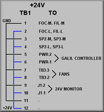
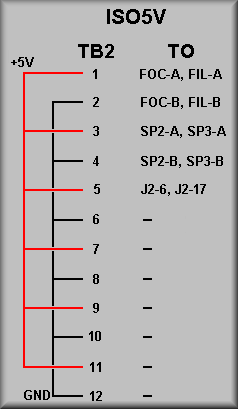
| FIG. 2 - TB1 +24V power wiring | Fig. 3 - TB2 +5V isolated power wiring |
| The +24V power supply is wired directly to a 12-position terminal strip TB1. The power supply is a Lambda part number SWS100-24. It supplies 24V at about 4 amps. The above table was used to do all of the 24V wiring. The abbreviations FOC, FIL, SP2, and SP3 stand for TV Focus, TV Filter Spare axis 2, and Spare axis 3MS-sytle connectors on the rear panel of the chassis. (Spare axis 1 is on the 8-channel Galil controller.) The Galil is powered via a Molex two pin Mate-n-lok connector with the polarity shown in the table. The 24V cooling fans are wired to TB3 which is supplied with 24V from TB1 7 and 8. The 24V supply voltage is monitored via the wires shown in the table. J1 refers to the connector on the Lick EL-1356 analog input card that plugs into the 'Analog' connector on the Galil. | The +5V isolated power supply, ISO5V, is wired directly to a 12-position terminal strip TB2. The power supply is a Lambda part number SWS100-5. It supplies 5V at about 20 amps. The above table was used to do all of the 5V wiring. The abbreviations FOC, FIL, SP2, and SP3 stand for TV Focus, TV Filter Spare axis 2, and Spare axis 3 MS-style connectors on the rear panel of the chassis. Terminal 5 provide the ISO5V input to the Galil signals LSCOM and INCOM on pins 6 and 17 of the General I/O connector J2.
|
schematics/HAM_II_box_2_wiring_sh_6.pdf
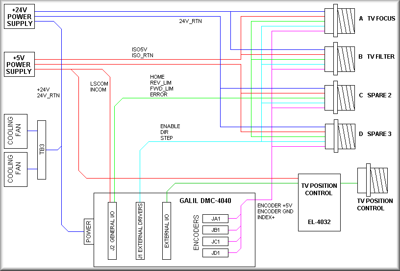
Fig. 4 One line drawing
Figure 4, the 'One Line Drawing' is provided for a quick overview of wiring inside the chassis.