Hamilton Spectrograph
This section contains descriptions of the electronics version 2 of the Hamilton Spectrograph.
8-Channel Chassis Wiring, EL-4003 ![]()
Schematic: schematics/HAM_II_box_wiring_sh_1.pdf
Page last updated: September 29, 2010
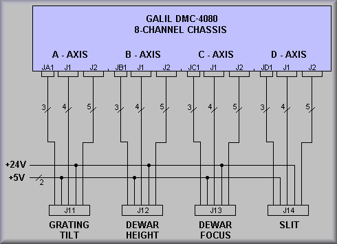
Fig. 1 - Simplified Drawing
schematics/HAM_II_box_wiring_sh_2.pdf ![]()
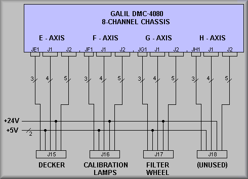
Fig. 2 - Simplified Drawing
Sheet 3, Iodine cell, 5th mirror, and 5th mirror cover wiring ![]()
schematics/HAM_II_box_wiring_sh_3.pdf
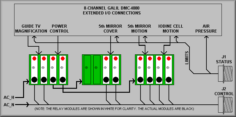
Fig. 3 - Simplified Drawing
Figure 3, Simplified Drawing, gives a quick idea of how the 5th mirror and iodine cell insert/retract stages work. For safety, the programmers asked to have the AC power to the mirror and iodine cell segregated from the mirror cover. This allows the software to interlock the mirror cover from the mirror and cell so that it can't open or close until the program applies power to the control modules. The signals that do this are DO41 (Digital Out 41) and DO42. DO41 turns on the mirror cover relay rack and DO42 turns on the 5th mirror and iodine cell relay rack. Obviously, these signals are levels whereas the remaining signals must be applied as pulses. Each of the other outputs are wired to pulse type air solenoids which are plumbed to Bimba cylinders. In each case, the cylinder is activated to either extend or retract depentent on which coil of the solenoid was last pulsed. The
schematics/HAM_II_box_wiring_sh_4.pdf
schematics/HAM_II_box_wiring_sh_5.pdf
Sheet 6, J1 Amplifier I/O connections - Axes A thru D ![]()
schematics/HAM_II_box_wiring_sh_6.pdf
GALIL |
TO |
Function |
GALIL |
TO |
Function |
|
|---|---|---|---|---|---|---|
| 1 Reserved | 23 Amp enable C | J13 - E |
DEWAR FOCUS | |||
| 2 PWM C/Step C | J13 - F |
DEWAR FOCUS | 24 NC | |||
| 3 Reserved | 25 +12V Out | |||||
| 4 Reserved | 26 Reserved | |||||
| 5 Sign C/Dir C | J13 - G |
DEWAR FOCUS | 27 Motor command C | |||
| 6 Reserved | 28 Reserved | |||||
| 7 Amp enable A | J11 - E |
GRATING TILT | 29 NC | |||
| 8 Amp enable D | J14 - E |
SLIT STAGE | 30 NC | |||
| 9 NC | 31 PWM B/Step B | J12 - F |
DEWAR HEIGHT | |||
| 10 -12V Out | 32 Reserved | |||||
| 11 Motor command B | 33 Ground | |||||
| 12 Reserved | 34 Sign B/ Dir B | J12 - G |
DEWAR HEIGHT | |||
| 13 NC | 35 Reserved | |||||
| 14 NC | 36 Ground | |||||
| 15 +5V Out | 37 Amp enable B | J12 - E |
DEWAR HEIGHT | |||
| 16 PWM A/Step A | J11 - F |
GRATING TILT | 38 Amp enable common 2 | |||
| 17 Reserved | 39 Ground | |||||
| 18 PWM D/Step D | J14 - F |
SLIT STAGE | 40 Motor command A | |||
| 19 Sign A/Dir A | J11 - G |
GRATING TILT | 41 Reserved | |||
| 20 Reserved | 42 Motor command D | |||||
| 21 Sign D/Dir D | J14 - G |
SLIT STAGE | 43 Ground | |||
| 22 Amp enable common 1 | 44 NC |
Table 1 shows the connections between J1 (axes A - D) and the rear stage connector. This consists of the ENABLE, STEP, and DIR signals.
Sheet 7, J1 Amplifier I/O connections - Axes E thru H ![]()
schematics/HAM_II_box_wiring_sh_7.pdf
GALIL |
TO |
Function |
GALIL |
TO |
Function |
|
|---|---|---|---|---|---|---|
| 1 Reserved | 23 Amp enable G | J17 -E |
SCIENCE FILTER WHEEL | |||
| 2 PWM G/Step G | J17 - F |
SCIENCE FILTER WHEEL | 24 NC | |||
| 3 Reserved | 25 +12V Out | |||||
| 4 Reserved | 26 Reserved | |||||
| 5 Sign G/Dir G | J17 - G |
SCIENCE FILTER WHEEL | 27 Motor command G | |||
| 6 Reserved | 28 Reserved | |||||
| 7 Amp enable E | J15 - E |
DECKER | 29 NC | |||
| 8 Amp enable H | J18 - E |
(UNUSED) | 30 NC | |||
| 9 NC | 31 PWM F/Step F | J16 - F |
CALIBRATION LAMPS | |||
| 10 -12V Out | 32 Reserved | |||||
| 11 Motor command F | 33 Ground | |||||
| 12 Reserved | 34 Sign F/Dir F | J16 - G |
CALIBRATION LAMPS | |||
| 13 NC | 35 Reserved | |||||
| 14 NC | 36 Ground | |||||
| 15 +5V Out | 37 Amp enable F | J16 - E |
CALIBRATION LAMPS | |||
| 16 PWM E/Step E | J15 - F |
DECKER | 38 Amp enable common 2 | |||
| 17 Reserved | 39 Ground | |||||
| 18 PWM H/Step H | J18 - F |
(UNUSED) | 40 Motor command E | |||
| 19 Sign E/Dir E | J15 - G |
DECKER | 41 Reserved | |||
| 20 Reserved | 42 Motor command H | |||||
| 21 Sign H/Dir H | J18 - G |
(UNUSED) | 43 Ground | |||
| 22 Amp enable common 1 | 44 NC |
Table 2 shows the connections between J1 (axes E - H) and the rear stage connector. This consists of the ENABLE, STEP, and DIR signals.
Sheet 8, J2 General I/O connections - Axes A thru D ![]()
schematics/HAM_II_box_wiring_sh_8.pdf
GALIL |
TO |
Function |
GALIL |
TO |
Function |
|
|---|---|---|---|---|---|---|
| 1 Error output | 23 Reverse limit B - isolated | J12 - I |
DEWAR HEIGHT | |||
| 2 Input 1 - isolated | J11 - N |
GRATING ERROR SIGNAL | 24 Reverse limit C - isolated | J13 - I |
DEWAR FOCUS | |
| 3 Input 4 - isolated | J14 - N |
SLIT ERROR SIGNAL | 25 Reverse limit D - isolated | J14 - I |
SLIT STAGE | |
| 4 Input 7 - isolated | 26 NC | |||||
| 5 Elect Lockout - Input - iso. | 27 Output 2 - isolated | |||||
| 6 Limit switch common - LSCOM | 28 Output 5 - isolated | |||||
| 7 Home A - isolated | J11 - J |
GRATING TILT | 29 Output 8 - isolated | |||
| 8 Home B - isolated | J12 - J |
DEWAR HEIGHT | 30 +5V out | |||
| 9 Home C - isolated | J13 - J |
DEWAR FOCUS | 31 Ground | |||
| 10 Home D - isolated | J14 - J |
SLIT STAGE | 32 Input 2 - isolated | J12 - N | DEWAR HEI. ERROR SIGNAL | |
| 11 Output power+ | 33 Input 5 - isolated | |||||
| 12 Output 3 - isolated | 34 Input 8 - isolated | |||||
| 13 Output 6 - isolated | 35 Ground | |||||
| 14 Output return | 36 Forward limit A - isolated | J11 - H |
GRATING TILT | |||
| 15 +5V Out | 37 Forward limit B - isolated | J12 - H |
DEWAR HEIGHT | |||
| 16 Reset - isolated | 38 Forward limit C - isolated | J13 - H |
DEWAR FOCUS | |||
| 17 Input common - INCOM | 39 Forward limit D - isolated | J14 -H |
SLIT STAGE | |||
| 18 Input 3 - isolated | J13 - N | DEWAR FOC ERROR SIGNAL | 40 Ground | |||
| 19 Input 6 - isolated | 41 Output 1 - isolated | |||||
| 20 Abort - isolated | 42 Output 4 - isolated | |||||
| 21 NC | 43 Output 7 - isolated | |||||
| 22 Reverse limit A - isolated | J11 - I |
GRATING TILT | 44 Output Compare A-D |
Table 3 shows the connections between J2 (axes A - D) and the rear stage connector. This consists of the HOME, FORWARD LIMIT, REVERSE LIMIT, and the Error signals. Note that the ERROR signal is generated by the Applied Motion ST5-S stepper driver box. If this is asserted a technician should physically look at the stage to see if there is a problem such as blown fuse. If nothing is obvious it may be useful to power cycle the drive box.
Sheet 9, J2 General I/O connections - Axes E thru H ![]()
schematics/HAM_II_box_wiring_sh_9.pdf
GALIL |
TO |
Function |
GALIL |
TO |
Function |
|
|---|---|---|---|---|---|---|
| 1 Error output | 23 Reverse limit F - isolated | J16 - I |
CALIBRATION LAMPS | |||
| 2 Input 9 - isolated | J15 - N |
DECKER ERROR SIGNAL | 24 Reverse limit G - isolated | J17 - I |
SCI. FILTER | |
| 3 Input 12 - isolated | J18 - N |
(UNASSIGNED) | 25 Reverse limit H - isolated | J18 - I |
(UNASSIGNED) | |
| 4 Input 15 - isolated | 26 NC | |||||
| 5 Elect Lockout - Input - iso. | 27 Output 10 - isolated | |||||
| 6 Limit switch common - LSCOM | 28 Output 13 - isolated | |||||
| 7 Home E - isolated | J15 - J |
DECKER | 29 Output 16 - isolated | |||
| 8 Home F - isolated | J16 - J |
CALIBRATION LAMPS | 30 +5V out | |||
| 9 Home G - isolated | J17 - J |
SCI. FILTER | 31 Ground | |||
| 10 Home H - isolated | J18 - J |
(UNASSIGNED) | 32 Input 10 - isolated | J16 - N | CAL LAMPS ERROR | |
| 11 Output power+ | 33 Input 13 - isolated | |||||
| 12 Output 11 - isolated | 34 Input 16 - isolated | |||||
| 13 Output 14 - isolated | 35 Ground | |||||
| 14 Output return | 36 Forward limit E - isolated | J15 - H |
DECKER | |||
| 15 +5V Out | 37 Forward limit F - isolated | J16 - H |
CALIBRATION LAMPS | |||
| 16 Reset - isolated | 38 Forward limit G - isolated | J17 - H |
SCI. FILTER | |||
| 17 Input common - INCOM | 39 Forward limit H - isolated | J18 - H |
(UNASSIGNED) | |||
| 18 Input 11 - isolated | J17 - N |
SCI. FILTER ERROR | 40 Ground | |||
| 19 Input 14 - isolated | 41 Output 9 - isolated | |||||
| 20 Abort - isolated | 42 Output 12 - isolated | |||||
| 21 NC | 43 Output 15 - isolated | |||||
| 22 Reverse limit E - isolated | J15 - I |
DECKER | 44 Output Compare A-D |
Table 4 shows the connections between J2 (axes E - H) and the rear stage connector. This consists of the HOME, FORWARD LIMIT, REVERSE LIMIT, and the Error signals. Note that the ERROR signal is generated by the Applied Motion ST5-S stepper driver box. If this is asserted a technician should physically look at the stage to see if there is a problem such as blown fuse. If nothing is obvious it may be useful to power cycle the drive box.
Sheet 10, Encoder Index connections - Axes E thru H ![]()
schematics/HAM_II_box_wiring_sh_10.pdf
GALIL LABEL |
TO |
FUNCTION |
GALIL LABEL |
TO |
FUNCTION |
|---|---|---|---|---|---|
| JA-1 MI+ | J1 - K |
FINE FIDUCIAL | JE-1 MI+ | J5 - K |
FINE FIDUCIAL |
| JA-5 GND | J1 - D |
ENCODER GND | JE-5 GND | J5 - D |
ENCODER GND |
| JA-15 +5V | J1 - C |
ENCODER +5V | JE-15 +5V | J5 - C |
ENCODER +5V |
| JB-1 MI+ | J2 - K |
FINE FIDUCIAL | JF-1 MI+ | J6 - K |
FINE FIDUCIAL |
| JB-5 GND | J2 - D |
ENCODER GND | JF-5 GND | J6 - D |
ENCODER GND |
| JB-15 +5V | J2 - C |
ENCODER +5V | JF-15 +5V | J6 - C |
ENCODER +5V |
| JC-1 MI+ | J3 - K |
FINE FIDUCIAL | JG-1 MI+ | J7 - K |
FINE FIDUCIAL |
| JC-5 GND | J3 - D |
ENCODER GND | JG-5 GND | J7 - D |
ENCODER GND |
| JC-15 +5V | J3 - C |
ENCODER +5V | JG-15 +5V | J7 - C |
ENCODER +5V |
| JD-1 MI+ | J4 - K |
FINE FIDUCIAL | JH-1 MI+ | J8 - K |
FINE FIDUCIAL |
| JD-5 GND | J4 - D |
ENCODER GND | JH-5 GND | J8 - D |
ENCODER GND |
| JD-15 +5V | J4 - C |
ENCODER +5V | JH-15 +5V | J8 - C |
ENCODER +5V |
Table 5.
Table 5 show the wiring for the FINE fiducials between the various Galil connectors and the stage connectors. Note that the FINE fiducial signal is referenced to the Galil's internal +5V supply. Also, the signal is used to trip the stage index input but is derived from Hall-effect sensor mounted to the shaft of the stage stepper motor. Only the Grating Tilt and Slit stages incorporate a FINE fiducial signal/sensor.
Sheet 11, Extended I/O signal assignments and wiring ![]()
schematics/HAM_II_box_wiring_sh_11.pdf
PIN |
I/O |
LABEL |
TO |
FUNCTION | PIN | I/O | LABEL |
TO |
FUNCTION |
1 |
I |
I/O18 |
J1-B |
5th mirror is extended (in beam) | 23 |
O |
I/O35 |
BRD2-7 |
Command 5th mirror cover to open (pulse) |
2 |
I |
I/O21 |
J1-E |
Mirror cover is closed | 24 |
O |
I/O37 |
BRD1-3 |
Command TV magnification to high |
3 |
I |
I/O24 |
J1-H |
Iodine cell is retracted (out of beam) | 25 |
NC |
|||
4 |
I |
I/O26 |
J1-K |
Iodine cell is in place (hall-effect sensor) | 26 |
O |
I/O40 |
BRD3-9 |
Command iodine cell extend (in beam) (pulse) |
5 |
I |
I/O29 |
- |
- | 27 |
O |
I/O43 |
- |
- |
6 |
I |
I/O32 |
- |
- | 28 |
O |
I/O46 |
- |
- |
7 |
O |
I/O33 |
BRD3-3 |
Command 5th mirror extend (in beam) | 29 |
O |
I/O48 |
- |
- |
8 |
O |
I/O36 |
BRD2-9 |
Command 5th mirror to cover close (pulse) | 30 |
3.3V |
|||
9 |
O |
I/O38 |
BRD1-5 |
Command TV magnification to low | 31 |
I |
I/O19 |
J1-C |
Iodine cell is extended (in beam) |
10 |
NC |
32 |
I |
I/O22 |
J1-F |
TV magnification is low | |||
11 |
O |
I/O41 |
BRD1-7 |
Set mirror cover power on (level) | 33 |
Ground |
- |
- | |
12 |
O |
I/O44 |
- |
- | 34 |
I |
I/O27 |
J1-L |
Air pressure is OK |
13 |
O |
I/O47 |
- |
- | 35 |
I |
I/O30 |
- |
- |
14 |
NC |
36 |
Ground |
- |
- | ||||
15 |
Reserved |
37 |
O |
I/O34 |
BRD3-5 |
Command 5th mirror extend (in beam) (pulse) | |||
16 |
I |
I/O17 |
J1-A |
5th mirror is retracted (out of beam) | 38 |
NC |
|||
17 |
I |
I/O20 |
J1-D |
5th mirror cover is open | 39 |
Ground |
- |
- | |
18 |
I |
I/O23 |
J1-G |
TV magnification is high | 40 |
O |
I/O39 |
BRD3-7 |
Command iodine cell retract(out of beam (pulse) |
19 |
I |
I/O25 |
J1-J |
Iodine cell is extended (in beam) | 41 |
O |
I/O42 |
BRD1-9 |
Set iodine power on (level) |
20 |
I |
I/O28 |
- |
- | 42 |
O |
I/O45 |
- |
- |
21 |
I |
I/O31 |
- |
- | 43 |
Ground |
- |
- | |
22 |
I |
NC |
44 |
NC |
|||||
|
Note: BRDn refers to the three Opto-22 relay racks in the 8-channel controller chassis. J1 is the 'Status' rear panel connector.
|
|||||||||
Sheet 12, J3 miscellaneous signals and wiring ![]()
schematics/HAM_II_box_wiring_sh_12.pdf