Dewar Monitor System Electronics
DMS RIO Software
Introduction
The UCO/Lick Observatory EL-5009 Dewar Monitoring System is used to monitor CCD dewars that have been removed from their mount and placed in the 120" dome basement. The system is designed to autonomously monitor the temperature of up to eight dewars and turn on an alarm if any experience a rise of more than about 5°C. In normal operation, the user can add or remove a dewar by connecting or disconnecting a DB25 connector to the dewar. The unit watches a signal line that is pulled down when a dewar is attached. When the signal goes low that channel is then monitored.
Software:
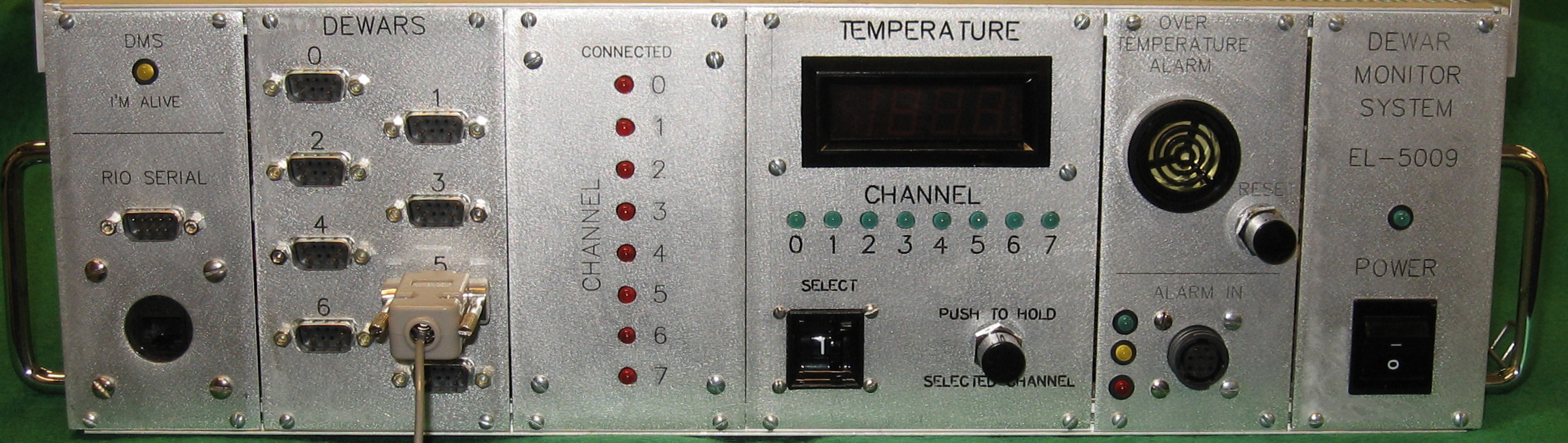
Click image for larger view
Click here for listing
The Galil control program to run the DMS, unlike other Lick controller software, lives directly on the RIO. This has been done several reasons. First, the DMS system needs to be a standalone system that is not dependent on the network or, for that matter, other equipment/resources. Secondly, the programming is not very complex and finally, the RIO471x2 has enough memory to hold the program. The program has three threads and two input generated interrupts. Thread0 is the main thread. Thread1 is the 'I'm Alive' thread that just blinks a yellow LED above the Comm connectors to indicate that the software is running. Thread2 is the 'Flash' thread that flashes the green channel-active LED at a fast rate to signify that that channel has warmed up. The first input interrupt, #ININT1, is the reset interrupt. It is triggered by pushing the 'RESET' button on the alarm front panel and resets any channels that have warmed up. The second input interrupt, #ININT2, is triggered when the 'SHOW CHANNEL' button is pushed. It stops execution of the main thread and directs the temperature of a single channel, selected by the paddle switch, to the 'TEMPERATURE' meter. When released the main program resumes from where it left off.
#DMSMAIN
This is the main loop. First, it jumps to the routine to check which channels have dewars connected and then it jumps to the the subroutine that checks the temperatures. Next, it performs a wait for 100 milliseconds then increments a counter of the times through the loop and then loops to the begriming and starts over.
#DMSINIT
This initialization routine sets up the RIO and the various arrays. It starts by configuring the analog inputs for +/-5V operation and then configures analog output #0 for +/-5V. This output drives the front panel meter. The next two lines turn off all of the software controlled front panel LEDs. The next 12 lines define the control variables. This includes the following:
- CYCL - the amount of time to wait before moving to the next channel. This must be long enough to allow the temperature meter readout to stabilize. The meter does not display its input instantaneously. Its almost like an analog meter in that it takes time for the display to come up to the full reading.
- WARM - this is the 5°C rise in temperature used to cause an alarm.
- TMPPTR - global pointer used to pass a pointer to the current temperature.
- GTEMP - global pointer used to pass a temperature to subroutines.
- HOT - a constant, 9.9999, used as the initial value for the 'coldest' entries in the history array.
The next 29 lines are devoted to the various arrays and pointers into those arrays. The history array is where all of the temperatures are stored. The first row contains the coldest temperatures archived and the second holds the average temperatures. The rest of the array is devoted to the latest n readings of each channel.
- HXSIZE - this is 8 as there are eight channels available to read.
- HYSIZE - this is currently 7. This is 1 for coldest, 1 for average, and 5 for temperature iterations.
- HSIZE - the size of the array.
The parameter array is used throughout the program for testing to see if a channel is active and to convert the analog input into a temperature. The array size is HXSIZE (8) times 5.
- ACTV - points to the first row of the array which out the active status for the channel.
- OFFSET - points to the second row which holds the zero offset for the temperature conversion.
- SLOPE - points to the third row which holds the slope for the temperature conversion.
- PARAM 8-15 are the measured zero offsets.
- PARAM 16-23 are the calculated slopes.
The BMASK array is used to bitwise operations.
The FLSHR array contains either 1 or -1 that tell the FLASH routine the state of the green LED if its channel has an active alarm.
The next 4 line of the initialization routine setup the email notification. It includes the mail server IP address, the address to send the email to, and the address that originated the email. The actual message is set in the #CKWARM routine.
The next 4 lines setup the interrupts and second and third threads as follows:
- Interrupt 1 is set to interrupt thread 1 when input 12, the RESET button, is pushed. See #ININT1.
- Interrupt 2 is set to interrupt thread 0 when input 11, the SHOW TEMPERATURE button, is pushed. See #ININT2.
- Thread 1 is started to flash the I'M ALIVE LED. (Remember, the main program runs in thread 0)
- Thread 2 is started to flash any channel (green) LED if it is in an alarm.
The last items in the init routine are to set T1 to the current RIO time, call the #CKCONNS routine and call the #SETARY routine. Note: the #SETARY is called twice to initialize the his troy array. There is a bug that hasn't been stepped on that causes problems when first initialized.
p>#SETARY
This routine initializes the history array. CTI and CTJ are setup to fill the array which has CTI*CTJ elements. Note that the RIO only recognizes single dimension arrays. HISTPTR is set to the product of CTI and CTJ to point to the current array element and then is checked to see if it is in the range of 0 to 7. If it is that means that the entry is for the 'coldest' channel element and set it to the HOT value. If the history pointer is greater than 7 then the element is assigned zero, thus zeroing all other elements in the array. The next order of business is to read in the temperatures of each active channel. The line:
CTI=HYSIZE-2;CTI=HYSIZE-CTI
effectively sets CTI to point at the third row of the array which is where the actual temperatures read in from the active channels starts. Then with CTJ zeroed, we set the HISTPTR to point at the next array element. With that done, we check to see if the current channel, PARAM[CTJ], is active and if so, copy CTJ into the global pointer TEMPPTR and call #CVTEMP which reads in and converts the analog input to a temperature that is returned in the global GTEMP. GTEMP is then added to the array and then we call #AVGCHAN to set the average array element for channel CTJ. However, if the channel is inactive, PARAM[CTJ]=0, we write a zero into the channel CTJ array element. The whole thing is looped through until the array is filled. Upon completion we exit the routine.
#CKCONNS
This routine simple checks the digital inputs 0-7 and sets the state of the PARAM[] element for each channel. Not that the state is set to 1 if the input is 0. DOH!
#CKTEMPS
This routine checks the incoming temperature. To do so, CHAN is used to count through the eight possible analog inputs. If the channel that CHAN points to is active, the following happens:
First, the green LED corresponding to the current channel is turned on.
Then we go through an elaborate backward counting scheme that moves the next-to-last temperature into the last temperature spot, the next-to-next-to-last temperature into the next-to-last spot and so on until we put the current temperature into the first spot. Maybe the diagram of the history array below makes it clearer!

So, once we've shifted the data in to the right spot, we then jump to the display routine, #DISPTMP, which limits the output to the meter to +/-5V. At this point the routine waits for a length of time defined by the variable CYCL that is set during the initialization. Then we jump to the #AVGCHAN subroutine which uses the current CHAN to point to the channel to be averaged. Finally, we jump to the #CKWARM subroutine that checks to see if the channel has risen more than 5°C (or the constant WARM).
At this point the CHAN value is incremented and checked to determine if we have cycled through all 8 channels. If so, this subroutine ends.
#AVGCHAN
Recalling the diagram above, the #AVGCHAN subroutine takes the average of all of the temperature elements for the channel it received in the TEMPPTR. It then calculates the average and saves it in the 'Average' element of the array (second box from left above).
In detail:
AVGPTR is set to 2; this points to the box above labeled Newest. It sets AVG1 to zero. AVG1 will hold the sum of the temperature elements. HISTPTR is set to point at the first element to add to the AVG1 sum. HISTPTR is the combination of AVGCT, or 2, times the number of analog channels available, 8, plus the current channel, CHAN. Thus, the starting point is after both the Coldest and Average boxes above plus the channel number. We loop through all of the elements by adding 8 to the AVGPTR until AVGPTR => HYSIZE.
At that point, we simply calculate the average using the sum, AVG1 divided by the number of iterations, HYSIZE-2. We set HISTPTR to the correct element for the average, HXSIZE, 8, plus the channel number and then save the average
#CVTEMP
This routine converts the analog input voltage to a temperature by adding or subtracting the zero offset and then dividing by the slope. The sign of the temperature is determined by comparing the offset to the analog voltage. The formulae in the diagram below, provided by Mingzhi Wei, show how to determine the sign of the temperature. Upon exiting the subroutine, the converted temperature is held in the global variable GTEMP.

#CKWARM
This routine checks to see if the channel passed to it in TEMPPTR has become WARM degrees, ~5°C, warmer than its coldest recorded temperature. If so, it sets the channel's alarm flag, ALRMFLG, turns on the sonalert, and sends an email to the mh-techs alias.
To begin, the routine sets pointers to the history array coldest and average elements, COLDPTR and AVPTR respectively. A simple comparison between the coldest recorded and the average + WARM is made to determine if the dewar has risen more than ~ 5°C. If it has, the following happens:
First, the ALFMFLG is checked to see if it has already been set. If not, the bit is set and the program jumps to a jump list that sends out the simple email telling which channel has warmed up. Once the subroutine completes, or if the ALRMFLG was set before re-entering #CKWARM, the sonalert is turned on via a SB9.
#DISPTMP
This routine just limits the analog signal sent to the front panel meter to a maximum of +/-5V.
#ININT1
This input interrupt routine is triggered when the front panel 'RESET' button (DI12) is pushed and interrupts thread1. Because we have two functions to the interrupt we start by saving the RIOs TIME value which will be used to determine if the button is held down more that 3 seconds. The first of these functions is to clear the alarm for any channels that have warmed up. The second, more draconian, function is to reset the entire history array and continue from there. From an operational standpoint, there is a danger in resetting the entire array: both the 'coldest' and 'average' entries are reset. The 'coldest' element is set to HOT, or 9.999, and the 'average' element is recalculate from 5 consecutive readings of the dewar. This 'average' is then copied into the 'coldest' element and thus there is no difference between the two so even though the dewar is warm the alarm routine does not see a 5 degree difference and no alarm is set. The danger here is that if multiple channels have warmed up and the operator causes a reset of the entire array the operator may miss that another channel has warmed up.
To clear an alarms the user selects the channel to clear via the paddle switch and then pushes the RESET switch.
#ININT2
This input interrupt routine is triggered when the front panel 'SHOW TEMPERATURE' button (DI11) is pushed and interrupts thread0. The first thing the routine does it to turn on the
#IMALIVE
This thread simply changes the state of the 'I'm Alive' LED on the front panel every 700 msecs. The flashing of the LED indicates that the software is running.
#CMDERR
This is an automatic subroutine that runs code when a DMC code error occurs. It is used to send info about the error that occurred. It also issues halts to threads 1 and 2.
#FLASH
This thread is used to flash the green LED for any channel that has warmed up and caused an alarm. Any channel that warms up has its ALRMFLG bit set. Thus, this thread mostly just runs in a tight loop until an ALRMFLG bit becomes set. If that happens the routine sets the counter FCT to zero and then uses it as a pointer into the BMASK array.