APF Spectrograph Electronics
Overall Block Diagram,  EL-3501
Schematic: schematics\APF_servo_sh_1.pdf
Page last updated: November 13, 2012
![]()
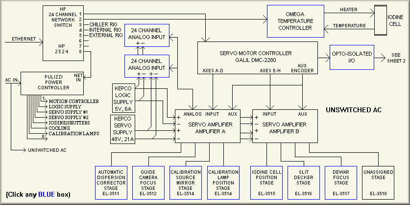
Simplified drawing (manual links used with permission from Galil)
The APF Spectrograph motion control system is shown on the first sheet of this schematic and in the simplified drawing above. The heart of the control electronics is the Galil DMC-2280 motion controller with its two AMP-19540 amplifiers. Via software, the controller manages the motion of the various stages using a dual loop encoding scheme where the high resolution load encoder provides position information and the motor encoder is The upper level stage control is programmed in the Linux PC that controls the instrument. The Linux PC interfaces the DMC controller with the outside world responding to the requests from the observing computer. A separate set of computers provided by the telescope manufacturer controls the movement of the telescope and dome. This write-up is concerned with only the spectrograph control.
At the left side of the drawing are the ethernet and AC connections. At the time of this writing, the HP 2524 router/hub is planned to be used to connect the to the various network capable components. The switch will provide communications with the Galil controllers, the Pulizzi power controller, and the Omega temperature controller that keeps the iodine cell at a constant temperature. The Galil controller will be discussed in the next paragraph. The link to the Pulizzi power controller allows the spectrograph control programming to turn on and off the various pieces of equipment in any order. As the telescope and spectrometer are meant to work autonomously, using the Pulizzi controller allows the software and/or support personnel to cycle power to specific equipment if needed. As a note, the control electronics system also has two programmable 8-channel AC controllers but these units are not network capable and instead are controlled via Galil I/O bits. At the top of the diagram, the Omega temperature controller is used to control the temperature of the iodine cell. It can be set up or interrogated over the network. See the user's manual (HERE). See our configuration (HERE). Also connected to the network switch are three Galil RIO,Remote I/O, controllers. These are discussed below.
Sheet 2,  APF_servo_sh_2.pdf
Simplified Drawing
Sheet 3, APF_servo_sh_3.pdf
Simplified Drawing
Sheet 4, APF_servo_sh_4.pdf
Simplified Drawing
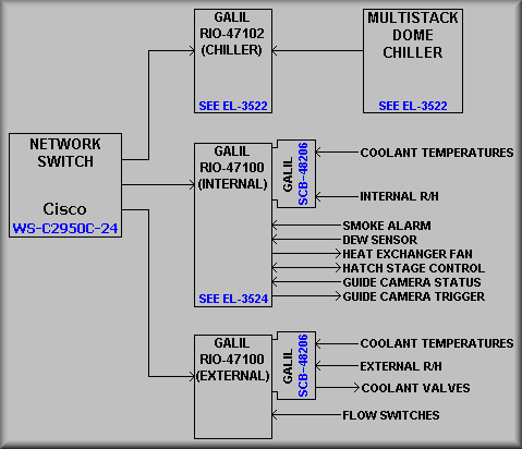
The above drawing shows the three Galil RIOs that are currently used by the APF control system. The top RIO is used exclusively for monitoring the dome chiller system. For a more complete description, see the EL-3522 write-up. Basically, the RIO monitors the alarm, the compressor normal operation signal, the compressor full load signal, and the compressor error condition signal. The middle RIO is mounted on the top surface of the spectrometer breadboard. It mainly controls the entrance hatch and monitors various environment sensors. The entrance hatch is described in detail in the EL-3524 write-up. It is basically a DC motor that runs the hatch between the open and closed positions. As shown, this RIO also monitors the various coolant circuit temperatures, the internal R/H sensor, the dew detector, and a smoke alarm. Lastly, this RIO also controls the cooling system fan that is mounted on the heat exchanger at the bottom of the spectrometer. Finally, the bottom RIO controls the proportional valves that allow the coolant flow through the four of the circuits associated with the spectrometer. These are the calibration lamp circuit, the heat exchanger circuit, and the UCAM controller circuit. Note that there is a fourth valve that is used as a bypass circuit in the event that the other circuits are closed or close to being closed. Also note that there are two other cooling circuits on the spectrometer. These are the Guide Camera circuit and the dewar circuit. These are each dedicated systems that rely on their on monitoring. See EL-3505 write-up for more details on the coolant systems. The bottom RIO also monitors the coolant temperature at the inlet manifold, the external R/H sensor, and the coolant flow switches. Communications with the control computer are through a network switch connected to the computer's private network card
Sheet 5, APF_servo_sh_5.pdf
Simplified Drawing
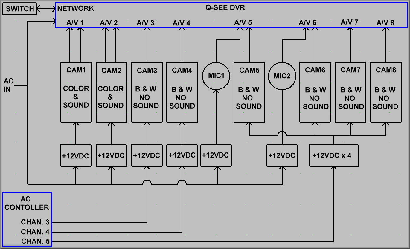
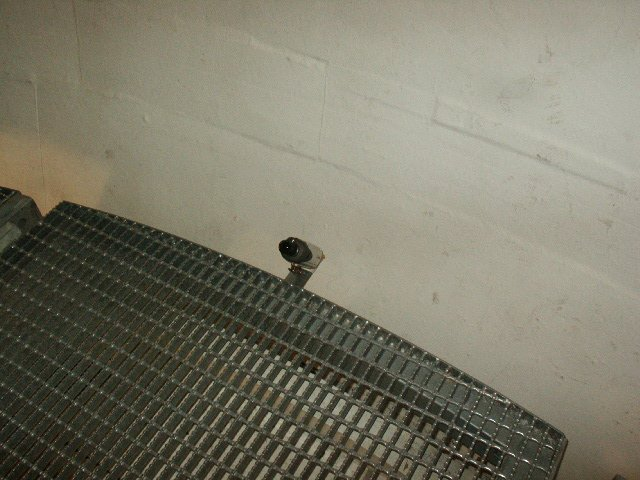
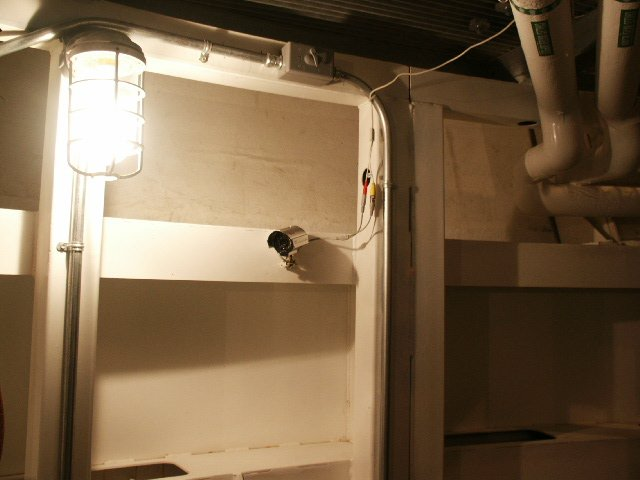
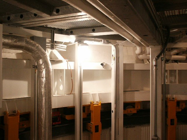
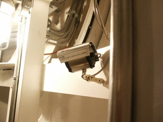
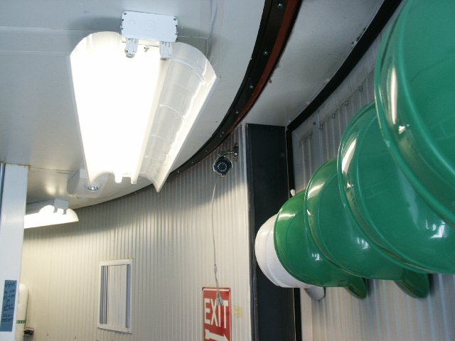
The above drawing shows the 7 remote cameras, the 2 microphones as well as the Q-See DVR (P/N QSTD2408) which is installed inside the APF dome. The DVR is located atop the EOS dome computer. Note that clicking in the Q-See blue box in the Simplified Drawing will bring up the User Manual for the system. The cameras are numbered CAM1, CAM2...CAM8. CAM1 and CAM2 are both color, have built in microphones, and are both installed on the level 3 of the dome. As shown in Photo 1 below, CAM1 is attached to the floor grating at the base of the slit and looks upward toward the telescope. Again, as shown in Photos 3 and 4 below, CAM2 is located on the dome wall above the work desk and points down at the mirror cover (when the telescope is pointed at the zenith). CAM3 and CAM4 are black and white with individually controlled power supplies, without microphones, and are equipped with infrared LEDs for night vision. CAM3 is located on level 3 and points at the work bench. CAM4 is located on level 2 and points at one of the azimuth drive motors. CAM5 is on level 3 and points at the floor area behind the telescope, as seen from the work desk area., CAM6 is on level 2 and points at the top of the stairway leading down to level 1. CAM7 is on level 1 and is pointed at the dome entrance door. It should be noted that CAM7 is mounted on the wall near the entrance door and does not rotates with the dome. Finally, CAM8 is located on level 2 and points at the "Dome Hitch" dome follower mechanism. There are two extra microphones installed on the audio inputs of CAM5 and CAM6. They are located on either side of the drive unit on level 2. Power for both CAM3 and CAM4 is independently controlled by output channels 3 and 4 respectively of the EL-1398 AC controller. The AC controller located inside the APF electronics rack. CAM5, CAM6, CAM7 and CAM8 are all black & white and are equipped with infrared LEDs. They are powered by a single +12VDC supply which is plugged into channel 5 of the AC controller. This means when you turn off the AC output channel 5, cameras 5-8 will all be turned off. (CAM1, CAM2 and both extra microphones, are not controlled by the AC controller and can not be turned off remotely. All cameras that have infrared LEDs can be remotely turned off so they won't flood the dome.
 |
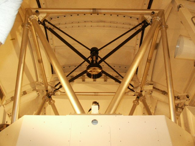 |
Photo 1 CAM1 Color & Sound |
Photo 2 Looking up at telescope. |
 |
 |
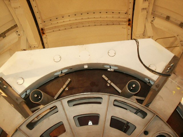 |
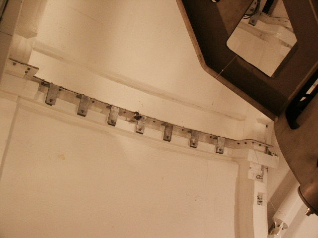
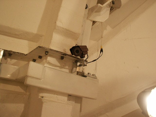
Photo 3 CAM2 Color & Sound |
Photo 4 CAM2 Color & Sound |
Photo 5 Looking down at telescope. |
 |
 |
Photo 6 CAM3 B&W |
Photo 7 Looking at work desk area. |
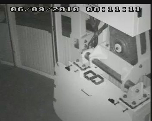 |
Photo 8 CAM4 B&W Looking at Dome Drive |
 |
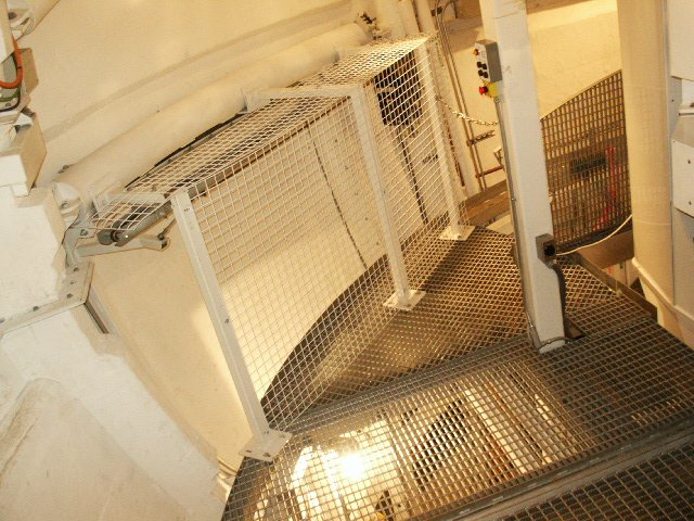 |
Photo 9 CAM5 B&W |
Photo 10 Looking at work opposite of desk. |
 |
 |
 |
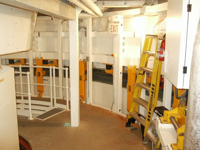 |
Photo 11 CAM6 B&W |
Photo 12 CAM6 B&W |
Photo 13 CAM6 B&W |
Photo 14 Views stairs coming up from 1st level |
 |
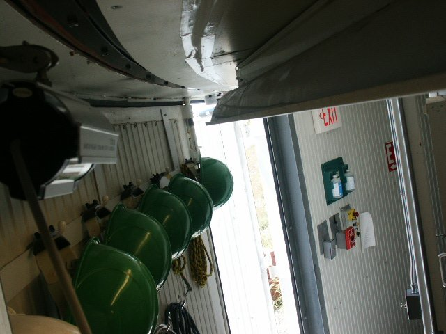 |
Photo 15 CAM7 B&W |
Photo 16 Looking at work opposite of desk. |
 |
Photo 17 CAM8 B&W Looking at the "Trailer Hitch" |
Sheet 6, APF_servo_sh_6.pdf
Simplified drawing
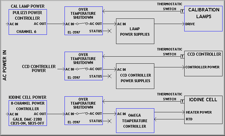
Sheet 6 shows a diagram of how the three over-temperature shutdown boxes fit into the APF's AC wiring scheme. They are used to shut down the AC power to any of the systems judged capable of creating dangerous amounts of heat within the spectrograph enclosure. The three systems that are connected to the boxes are:
- The calibration lamp system
- The CCD controller
- The iodine cell controller
The calibration lamp system receives AC power via channel 6 of the Pulizzi IPC3402-NET AC power controller. This channel is normally left in the on state allowing the APF control software to directly turn on or off the power supplies of each individual lamp, both the quartz and thorium main lamps and their backup lamps. The control software also monitors the temperature at various locations inside the spectrograph, most importantly are the RTD on the calibration lamp cooling line and the solid-state sensor on the integrating sphere. The control software is set to turn off the lamps if the temperature rises too high on either of these sensors. As a failsafe measure, an 85°F Selco normally open thermostatic switch is mounted to the integrating sphere. This switch feeds back to the over-temperature shutdown box and causes power to be disconnected from the lamp power supplies. Once this happens, a pulsing Sonalert turns on to get the operator's attention. Lamp AC power will remain off and the Sonalert will remain on until two conditions are met. First, the thermostatic switch bimetal element must cool by as much as sixteen degrees to reset to the open condition and second, either the red 'Reset' button on the front of the shutdown box must be pressed or the AC power into the shutdown box must be cycled.
The UCAM CCD controller chassis has been modified for use in the APF instrument by adding a small cooling coil to the chassis interior. This coil is meant to remove excessive heat from the spectrograph. Again, as a failsafe, a Selco CA85 thermostatic switch has been mounted to the exterior of the box. If the box temperature rises above the trip point, 85° ±7°, power will be removed from the UCAM power supply box. If it trips, follow the procedure in the above paragraph.
When in use, the iodine cell is heated to 50 ° C. A network capable Omega CNi833-EL temperature controller is used to control the heater. Per schematics EL-3515 sheet 4, three heater elements are wired in series to heat the cell. An RTD is used for temperature feedback and a 160° F thermostatic switch is mounted inside of the cell to keep the cell from over heating. Besides the internal switch, a Selco CA85 has been added to the outside surface of the cell. It works in the same fashion as the calibration lamp system above. Note that the control computer can cycle the input power to the over-temperature box by cycling the DMC's I/O bit 35.